Lecture 22 : Logical Effort Calculation of few Basic Logic Circuits
22.1 Introduction
The method of logical effort is an easy way to estimate delay in a CMOS circuit.
We can select the fastest candidate by comparing delay estimates of different logic
structures. The method also specifies the proper number of logic stages on a path and the
best transistor sizes for the logic gates. Because the method is easy to use, it is ideal for
evaluating alternatives in the early stages of a design and provides a good staring point
for more intricate optimizations. It is founded on a simple model of the delay through a
single MOS logic gate. The model describes delays caused by the capacitive load that the
logic gate drives and by the topology of the logic gate. Clearly as the load increases, the
delay increases, but the delay also depends on the logic function of the gate. Inverters, the
simplest logic gates, drive loads best and are often used as amplifiers to drive large
capacitances. Logic gates that compute other functions require more transistors, some of
which are connected in series, making them poorer than inverters at driving current. Thus
a NAND gate has more delay than an inverter with similar transistor sizes that drives the
same load. The method of logical effort quantifies these effects to simplify delay analysis
for individual logic gates and multistage logic networks.
The method of logical effort is founded on a simple model of the delay through a
single MOS logic gate. The model describes delay caused by the capacitive load that the
logic gate drives. Certainly as the load increases the delay increases, but delay also
depends on logical function of the gate. Invertors, the simplest logical gates, drive loads
best and are often used as amplifiers to drive large capacitances. Logic gates that
compute other functions require more transistors, some connected in series, making them
poorer than inverters at driving currents. Thus NAND gate has more delay than inverter
with similar transistor size and driving load. The method of logical effort qualifies these
effects to simplify delay analysis for individual logic gates and multistage logic networks.
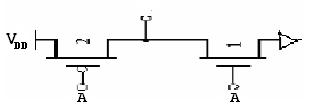
22.2 Logical Effort of an Inverter
The logical effort of an Inverter is defined to be unity.