Lecture 16 : Propagation Delay Calculation of CMOS Inverter
Contd...
From figure (16.32) while in saturation,
Integrating from t = t1, corresponding to Vout=0.9 VDD, to t = t2 corresponding to Vout=(VDD-Vtn) results in,
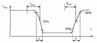
Fig 16.34: Rise and Fall time graph
When the n-device begins to operate in the linear region, the
discharge current is no longer
constant. The time tf1 taken to discharge the capacitor voltage from (VDD-Vtn) to 0.1VDD can be
obtained as before. In linear region,
Thus the complete term for the fall time is,
The fall time tf can be approximated as,
From this expression we can see that the delay is directly proportional to the load capacitance.
Thus to achieve high speed circuits one has to minimize the load capacitance seen by a gate.
Secondly it is inversely proportion to the supply voltage i.e. as the supply voltage is raised the
delay time is reduced. Finally, the delay is proportional to the βn of the driving transistor so
increasing the width of a transistor decreases the delay.