Lecture 9 : Graphical Approach for Transmission Analysis
Constant Reactance Circles
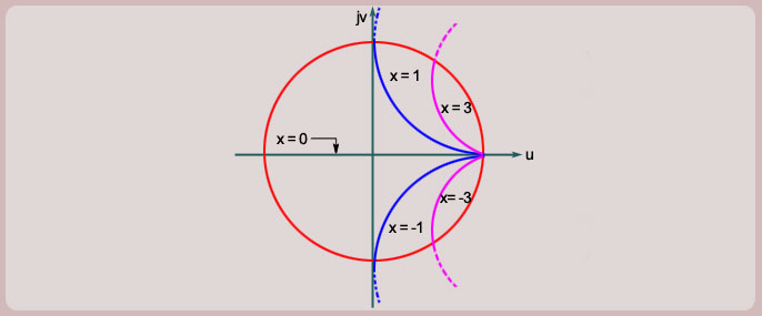
The constant reactance circles have their centers at and radii . The centres for these circles lie on a vertical
line passing through point (1,0) in the -plane. The constant reactance circles are shown in figure below for different
values of
Note again that only those portions of the circles are of significance which lie within the unity circle in the -plane.
The curves shown dotted portion do not correspond to any passive load impedance.
We can note following things about the constant reactance circles:
(a)
These circles have their centers on a vertical line passing through point .
(b)
For positive the center lies above the real -axis and for negative , the center lies below the real -axis.
(c)
For the center is at and radius is .This circle therefore represents a straight line.
(d)
As the magnitude of the reactance increases the center moves towards the real -axis and it lies on the real
-axis at (1,0) for .
(e)
As the magnitude of the reactance increases, the radius of the circle, ,decreases and it approaches zero as .
(f)
All circles pass through the point .
(g)
The real -axis ( -axis) corresponds to and therefore represents real impedances, i.e., purely
resistive impedances.
(h)
The right most point on the unity circle, , corresponds to as well as .