Module 2 : Transmission Lines
Lecture 9  : Graphical Approach for Transmission Analysis
            The graphical representation given in the following mainly describes the impedance/admittance characteritics of a
             transmission line.
 
Complex Impedance (Z) & Reflection co-efficient ( ) planes
   
Let us define the normalized impedance
 
For passive loads
  and
A passive load can be denoted by a point in the right half of the complex Z-plane as shown in Fig(a)
The complex Reflection Coefficient is

The complex can be expressed in cartesian and polar form as
 
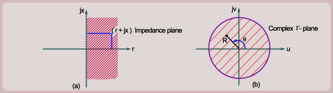
Since for passive loads , the reflection coefficient can be denoted by a point with the unity circle in the complex - plane, as shown in Fig (b). 'R' denotes the magnitude of the reflection coefficient and denotes the phase of the reflection coefficient.
Since there is one-to-one mapping between to , the entire right half Z-plane is mapped on to the region within the unity circle in the -plane.