The sign ± in the second line in eqn.(9) corresponds to electrons (holes) in the semiconductor. The above equations are valid only for a small change in μ±. In order to treat drift and diffusion at the same time, an electrochemical potential ![]() should be introduced. Here, φ is the electric scalar potential. By using
should be introduced. Here, φ is the electric scalar potential. By using ![]() , the charge current density in each spin sub-channel can be expressed simply as follows:
, the charge current density in each spin sub-channel can be expressed simply as follows:
|
(10) |
The total spin and charge current densities can be expressed in terms of the current densities appearing in eqn.(10) as
|
|
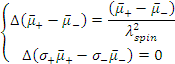
For a given constant current, the growth of the spin accumulation continues until it balanced by spin diffusion and relaxation, and, then the system falls into a steady state. In the steady state, we obtain the following set of equations from eqns. (5), (6), (10) and (11):
|
|
| where
|
|
Here, Δ is the Laplacian, λ± is the spin diffusion length in each spin sub-channel, λspin is the average spin diffusion length. Eqn. (13) is solvable easily and used to evaluate spin-dependent transport in the diffusive regime by considering the boundary conditions. In the simplest model, we assume the continuity of the electric current density, spin current density and electrochemical potential at the interface. If there is a particular spin relaxation at the interface, the discontinuity of the spin current density must be considered. On the other hand, for tunnelling junctions, the discontinuity of the electrochemical potential caused by spin-dependent interface resistances must be taken into account. Under this condition, spin polarization of the injected current is calculated as follows: