Physical Origin of GMR :
There are two principal geometries of the GMR effect, which are schematically shown in Figure 25.2. In the first case (Figure 25.2a), the current in the samples flows perpendicular to the multilayers, called as current perpendicular to the plane (CPP) geometry, whereas in the Figure 25.2b, the current flows in the plane of the layers and the geometry is termed as current in the plane (CIP). Interestingly, the underlying physical mechanism is the same for both CPP and CIP geometries. Let us consider a trilayer magnetic film with two magnetic layers separated by a non-magnetic metallic spacer layer. The electron spin is conserved over distances of up to several tens of nanometers, which is larger than the thickness of a typical multilayer. Thus, we may assume that the electric current flows in two channels, one corresponding to electrons with spin↑direction and the other to the electrons with spin↓ directions [3]. Since the spin channels are independent, they can be regarded as two wires connected in parallel. Also, when the electrons enter the FM layer, they are scattered at different rates due to directions of spin alignment (parallel and antiparallel) with respect to the magnetization of the FM layer. This is called as spin-dependent scattering.
Let us assume that electrons with spin antiparallel to the magnetization are scattered more strongly. The GMR effect in a trilayer can be now explained qualitatively using a simple resistor model shown in Figure 25.3. In the FM configuration, electrons with ↑spin are weakly scattered both in the first and second FM whereas the↓spin electrons are strongly scattered in both FM layers. This can be simulated by two small resistors in the ↑ spin channel and by two large resistors in the↓spin channel in the equivalent resistor network shown in Figure 25.3a. Therefore, the resistance in FM configuration is determined by the low-resistance ↑spin channel which shorts the high-resistance↓spin channel. On the other hand,↓spin electrons in the AFM configuration are strongly scattered in the first FM layer but weakly scattered in the second FM layer. The ↑spin electrons are weakly scattered in the first FM layer and strongly scattered in the second. This is schematically modelled in Figure 25.3b by one large and one small resistor in each spin channel. There is no shorting now and the total resistance in the AFM configuration is much higher than that in the FM configuration.
This simple resistor model of the GMR effect is believed to be correct to understand the overall behaviour. However, we need to involve a quantitative theory that can explain the differences between the CIP and CPP geometries, the observed dependence of the GMR on the layer thicknesses and also the material dependence of the effect, which is beyond the scope of the present lecture. Also, one needs to understand different types of scattering that the electrons experience in magnetic multilayer. Typically, the scatterings due to the impurity spin at the interface, scattering from the spin waves, and strong spin-orbit interaction mix the↑and ↓spin channels, which is detrimental to the GMR. Following the resistor network theory of GMR [4] in periodic superlattice, the change in the resistance in multilayer films can be defined as,
|
(25.2) |
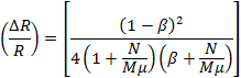
Where,  is a constant defined as the ratio between the low resistivity for the same (parallel) spin orientation configuration,
  , and high resistivity for the anti-parallel spin orientation configuration,
  , and
, and  is the ratio of the low resistivity for the same (parallel) spin orientation configuration, , to the resistivity of the NM layer.