Pattern Analysis:
The arrangement of atoms depends on how the crystal is cut.
Figure 7.06 shows the typical example of schematic representation of three different surfaces of a face-centered cubic (fcc) metal.
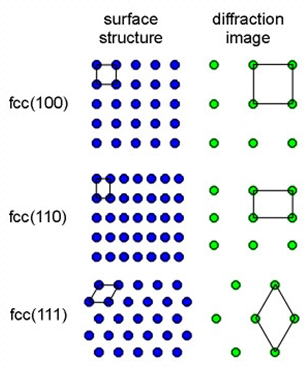
Figure 7.06: Schematic of surface structure and diffraction image for fcc structure.
The black polygons show the unit cell (smallest unit of surface) and reveal how the diffraction image appears. One important occurrence observed is that the long side of the 110 surface unit cells transform to the short side of the unit cell in the diffraction image.
The typical disadvantage of LEED is that close to normal incidence of the beam is necessary. Therefore, one can not control the surface geometry, i.e., during film growth (epitaxy). For this purpose RHEED is used.