Let us now see the meaning and significance of each block of the program.
Block 1 to 4: Preparatory functions and commands.
Block 5: In CNC turning, only two axes viz. X and Z are used. X axis is along the radius of work part, whereas Z axis is along the length of the work part. Figure 7.4.2 shows the axes system used in CNC turning centers. The program zero will be set by using G54 command. The program zero is assumed to be located at the tip of work contour as shown in Figure 7.4.1.
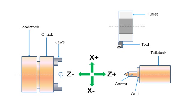
Figure 7.4.2 Axes system used in CNC turning center
Block 6: In turning programming the Tool is designated by an alphabet ‘T’ and four numerals. Out of the four numerals, first two indicates the tool number and the last signifies the wear offset number. In this block the tool number 1 is selected.
Block 7: G96 command maintains the constant surface speed during the reduction of diameter by using CNC turning. For efficient and proper cutting, it is essential to maintain a constant cutting speed (along the surface). It can be obtained by varying the spindle RPM according to the change in the diameter during the turning operation. Figure 7.4.3 shows that how the RPM of the spindle should be increased to maintain the constant surface speed.
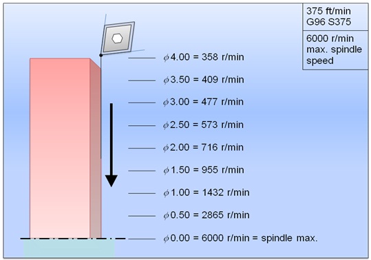
Figure 7.4.3 Constant surface speed control