Block 9:
In the given task, number of holes is to be drilled. For this purpose a special function or cycle is used. It is called as drilling canned cycle. Its syntax and meaning are shown below. The number of motions/action elements of drilling operations is specified only at once. Later only the locations of holes to be drilled are given to the MCU.
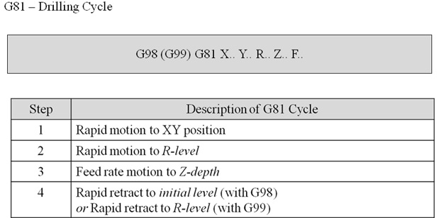
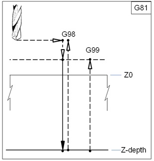
Figure 7.2.7 Drilling canned cycle.
Block 10:
It suggests the distance of next location of the hole. It is also suggested to carry out the same drilling operation 6 times along the Y-axis with an increment of 2.1.
Block 11:
Drill the hole at increment of 1.8 along X-direction.
Block 12:
Carry out the drilling operation 6 times along the Y-axis with decrement of 2.1.
Block 13:
Drill the hole at increment of 1.8 along X-direction.
Block 14:
Carry out the drilling operation 6 times along the Y-axis with increment of 2.1.
Block 15:
Drill the hole at increment of 1.8 along X-direction.
Block 16:
Carry out the drilling operation 6 times along the Y-axis with decrement of 2.1.
Block 17:
Drill the hole at increment of 1.8 along X-direction.
Block 18:
Carry out the drilling operation 6 times along the Y-axis with increment of 2.1.
Block 19:
Cancel the canned cycle and switch off the coolant flow.
Block 20:
Stop the spindle and go to safe position along Z direction at 0.0.
Block 21:
Go to home position via X= 0 and Y=0.
Block 22:
Stop the program from execution.
Block 23:
End the program.