As name indicates, in binary weighted DAC, output voltage can be calculated by expression which works on binary weights. Its circuit can be realized in Figure 2.8.3. From the figure it can be noted that most significant bit of digital input is connected to minimum resistance and vice versa. Digital bits can be connected to resistance through a switch which connects resistance-end to the ground . The digital input is zero when former bit is connected to reference voltage and if it is 1. This can be understood from Figure 2.8.4. DAC output voltage can be calculated from property of operational amplifiers. If V1 be input voltage at MSB (most significant bit), V2 be input voltage at next bit and so on then for four bit DAC we can write,
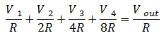 |
(2.8.1) |
Note: Here V1, V2, V3, V4, will be Vref if digital input is 1 or otherwise it will be zero.
Hence output voltage can be found as:
| (2.8.2) |
However Binary weighted DAC doesn't work for multiple or higher bit systems as the value of resistance doubles in each case.
Thus simple and low bit digital signals from a transducer can be converted into a related continuous value of voltages (analogue) by using binary weighted DAC. These will further be used for manipulation or actuation.
4.2 R-2R Ladder based DAC
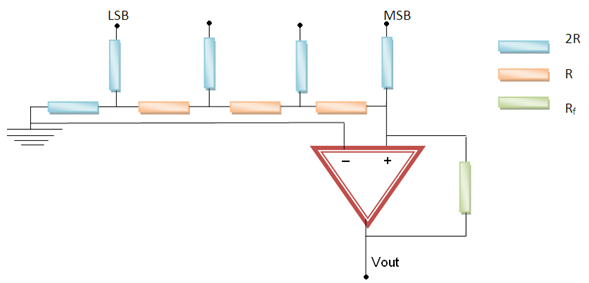
Figure 2.8.5 R-2R Ladder based DAC
In R-2R ladder logic, shortcoming of Binary Logic has been removed by making the value of maximum resistance double however the rest of the circuit remains same.Figure 2.8.5 shows the circuit of R-2R Ladder based DAC. If we apply voltage division rule in above case, then we can calculate that output voltage as,
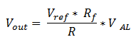 |
(2.8.3) |
Where VAL can be calculated from the digital signal input as,
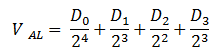 |
(2.8.4) |
In this way output voltage is obtained by converting the digital signals received from microprocessor/ microcontroller. These voltages will further be used to actuate the desired actuator viz. DC/AC motors.
In this module we have studied the principle of operation of various sensors which are commonly used in mechatronics and manufacturing automation. Also the signal conditioning operations and the devices which are used to generate the proper signals for desired automation application have been studied. In the next module we will study the construction and working of microprocessor and the devices which are being used in controlling the various operations of automation using the microprocessors.