Data Conversion Devices are very important componentsof a Machine Control Unit (MCU). MCUs are controlled by various computers or microcontrollers which are accepting signals only in Digital Form i.e. in the form of 0s and 1s, while the signals received from signal conditioning module or sensors are generally in analogue form (continuous). Therefore a system is essentially required to convert analog signals into digital form and vis-à-vis. Analog to Digital Converter is abbreviated as ADC. Figure 2.8.1 shows a typical control system with data conversion devices.
Based on the signals received from sensors, MCU generates actuating signals in the Digital form. Most of the actuators e.g. DC servo motors only accept analogue signals. Therefore the digital signals must be converted into Analog form so that the required actuator can be operated accordingly. For this purpose Digital to Analog Converters are used, which are abbreviated as DACs. In subsequent sections we will be discussing about various types of ADC and DAC devices, their principle of working and circuitry.
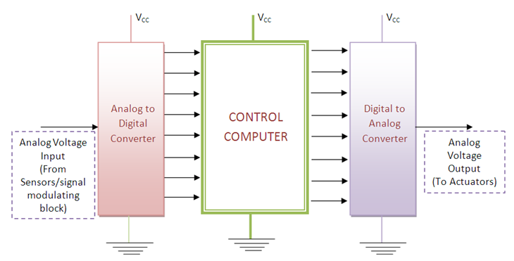
Figure 2.8.1 A control system with ADC and DAC devices
Basic components used in ADCs and DACs
1. Comparators
In general ADCs and DACs comprise of Comparators. Comparator is a combination of diodes and Operational Amplifiers. A comparator is a device which compares the voltage input or current input at its two terminals and gives output in form of digital signal i.e. in form of 0s and 1s indicating which voltage is higher. If V+ and V- be input voltages at two terminals of comparator then output of comparator will be as
V + > V - → Output 1
V + < V - → Output 0