The perspective is drawn using the top and Front view.
- First the Front view and top view of the hexagonal lamina is drawn in the third angle projection.
- Construct the hexagon in the top view keeping point a 25 mm above PPP and edge ab inclined at 50° to PPP. Label the corners of the hexagon in the top view as a, b, c, d, e, and f.
- Project the front view on to the GL and obtain the points a’, b’ c’, d’ e’ and f’.
- Locate S 80 mm left of point a and 50 mm below PPP.
- Locate S’ 60 mm above GL by drawing projector from S.
- Draw line from S and passing through point a, b, c, d, e, and f in the top view.
- Label the intersection points of these lines PPP as a1, b1, c1, …, f1, respectively.
- Draw line from S’ and passing through point a’, b’ c’, d’ e’ and f’ in the front view.
- Draw vertical projectors from a1, b1, c1, d1, e1 and f1 so as to intersect the lines s’-a’, s’-b’, …, s’-f’ at points A, B, C, D, E, and F. Joint A-B-C-D-E-F to obtain the perspective.
Problem 2.
A square pyramid 5 cm base edge and axis 6 cm high, rest on the base with one edge of the base parallel to and 3 cm behind the picture plane. The central plane is 5 cm to the right of the apex. The station point is 5cm in front of the picture plane and 3 cm above the ground plane. Draw the perspective of the pyramid by visual ray method.
Solution: The step wise method of drawing the perspective view by visual ray method is shown in figure 5.
- First, draw the Top view and Front view by the 3rd angle projection. The top view of the picture plane is PPP. The top view of the edge a-b of the pyramid is 3 cm above PPP. Draw the central plane, i.e. a vertical passing through O in both Front view and top view.
- Locate the station point in the front view and top view. Top view of station point, S is 5 cm towards the right of Central plane and 5 cms below PPP. Front view of station point, S’ is 3 cm
- above GL and passing through the vertical projector through S.
- Draw lines joining the Top view of the station point S to the Top view of the object points a, b, c, d, and o.
- Joint the front view of the station point S’ with the Front view of the object points A,B,C,D, O.
- In the Top view the points at which the visual rays penetrate the picture plane (PPP) are a1, b1, c1, d1 and o1. These are the top views of the perspective points.
- Vertical projectors through these points should pass through the Front views of the perspective points. Hence the vertical projectors through points a1, b1, c1, d1 and o1 should intersect the respective visual rays from S’ in the Front View., These points are A1, B1, C1, D1, and O1 respectively in the Perspective view.
- We can also obtain the perspective view by projections from the Top View and Side view.
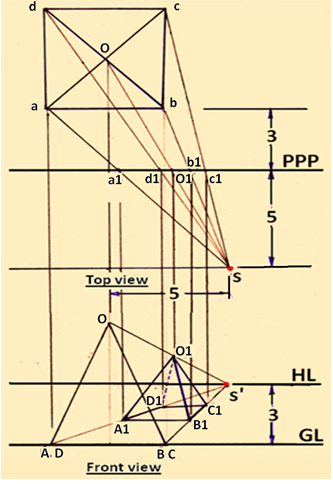
Figure 5. Step wise method of drawing the perspective view for problem 1.