Figure 2 shows the front view (view along the direction indicated by the arrow) of a solid and hollow cylindrical object. The front view of the solid cylinder is seen as a rectangle (figure 2(a)). For the hollow cylinder in addition to the rectangle representing the boundary of the object, two dashed lines are shown to present the boundary of the hole, which is a hidden feature in the object.
Figure 3 shows the Front view of three objects. Figure 3(a) is the view of one part of a hollow cylinder which has been split in to two equal parts. The wall thickness can be represented by the two visible lines. Figure 3(b) is one part of solid cylinder which has been sectioned in to two equal part. Where as figure 3(c) is one part of a solid cylindrical part which has been split in to two unequal parts. The edge formed by the intersection of two surfaces are represented by solid lines. In case of cylindrical objects or when holes are present in a component, the centre of the holes or centre lines of cylinder will have to be represented in the drawing by means of centre lines as shown in figure 4. Figure 5 shows the FV, TV, and RHSV of an object showing visiblke edges, hidden edges (or holes), and centre lines.
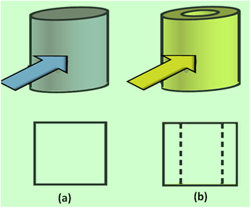
Figure 2 shows the pictorial view and front view of (a) a hollow cylindrical object and (b) solid cylindrical object.
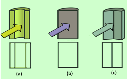
Figure 3 shows the pictorial view and front view of sectioned part of (a) a hollow cylindrical object (b) solid cylindrical object and (c) solid cylinder split in to two unequal parts.
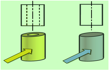
Figure 4 shows the centre lines for cylindrical objects
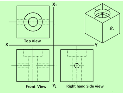
Figure 5. Showing TV, FV and RHSV of an object showing the three types of lines mentioned above. The pictorial view of the object is shown at the top hight hand side.