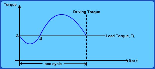
When an IC engine is used as a prime mover, the driving torque available at the crank shaft may not in general match the load torque demanded from instant to instant. For example, if the load torque is uniform with respect to time, the load and driving torque will have same value in an average (or mean) sense as shown in Fig. 5.3 but won't match at every instant of time. For steady state operation, it is required that over a cycle average torques match. In other words we can say:
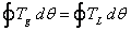 (5.6)
If on an average, the load torque over each cycle is more than the supply torque, system will soon come to a halt.
If on an average, the load torque over each cycle is less than the supply torque, system speed will keep increasing indefinitely.
If on an average, the load torque over each cycle is equal to the supply torque, system will operate in a steady state.
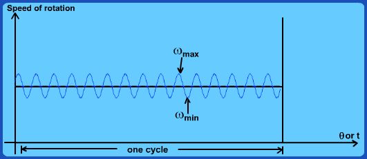
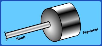
However even if the average torques match, in the portion of the cycle when the load torque is instantaneously smaller than driving torque, there will be instantaneous acceleration of the crank shaft. When the load torque momentarily exceeds the driving torque available, crank shaft will decelerate. Thus even though the crankshaft has a “steady” speed of rotation, there will be small fluctuations in speed within each cycle as shown in Fig. 5.4. At steady state, the same cycle will of course repeat itself. We wish to minimize the speed fluctuations, to the extent possible. This is achieved through the addition of a flywheel to the system shaft as shown in Fig. 5.5.
|