For the purpose of gas torque analysis, let us assume for the time being that all the links have negligible mass and ignore any inertia force affects. Of course some of the gas torque will have to be used to overcome the inertia of the moving parts. From the free body diagram shown in Fig. 5.2 and the considerations of static equilibrium, we find that the normal force on the cylinder frame at the piston is given by:
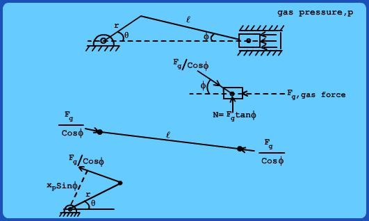
Figure 5.2 Free Body Diagram for gas Pressure loading
 (5.1)
Similarly the force transmitted through the connecting rod is given by:
 (5.2)
Taking moment of this force on the crankshaft pivot, we get the gas torque as:
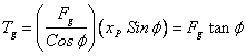 (5.3)
From the geometry of the IC Engine mechanism, we can write
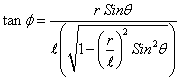 (5.4)
Thus the gas torque varies as a complex function of time (since  , where  is the speed of rotation).
|


