CONNECTING ROD
One end of the connecting rod is circling while the other end is reciprocating and any point in between moves in an ellipse. It is conceivable that we derive a general expression for the acceleration of any point on the connecting rod and hence estimate the inertia forces due to an elemental mass associated with that point. Integration over the whole length of the connecting rod yields the total inertia force due to the entire connecting rod. Instead we try to arrive at a simplified model of the connecting rod by replacing it with a dynamically equivalent link as shown in Fig 3.6.
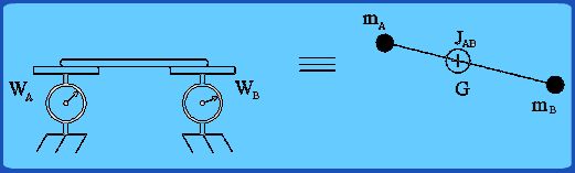
Figure 3.6 Dynamically Equivalent link for a connecting rod .
In order that the two links are dynamically equivalent, it is necessary that:
 Total mass be the same for both the links Total mass be the same for both the links
Distribution of the mass be also same i.e., location of CG must be same and the mass moment of inertia also must be same.
Thus we can write three conditions:
 (3.11) (3.11)
For convenience we would like the equivalent link lumped masses to be located at the big and small end of the original connecting rod and if its center of mass (G) location is to remain same as that of original rod, distances AG and GB are fixed. Given the mass m and mass moment of inertia  of the original connecting rod, the problem of finding dynamically equivalent link is to determine of the original connecting rod, the problem of finding dynamically equivalent link is to determine  , ,  and and  . .
An approximate equivalent link can be found by simply ignoring  and treating just the two lumped masses and and treating just the two lumped masses and  connected by a mass-less link as the equivalent of original connecting rod. In such a case we take: connected by a mass-less link as the equivalent of original connecting rod. In such a case we take:
 = =  (GB)/L (GB)/L
 = (AG)/L (3.12) = (AG)/L (3.12)
Thus the connecting rod is replaced by two masses at either end (pin joints A and B) of the original rod.  rotates along with the crank while rotates along with the crank while  purely translates along with the piston. It is for this reason that we proposed use of crank's effective rotating mass located at pin A, which can now be simply added up to part of connecting rod's mass. purely translates along with the piston. It is for this reason that we proposed use of crank's effective rotating mass located at pin A, which can now be simply added up to part of connecting rod's mass.
On the shop floor , can be immediately determined by mounting the existing connecting rod on two weighing balances located at A and B respectively. The readings of the two balance give and directly |