If we remember the controller design in continuous domain using root locus, we see that the design is based on the approximation that the closed loop system has a complex conjugate pole pair which dominates the system behavior. Similarly for a discrete time case also the controller will be designed based on the concept of a dominant pole pair.
Controller types: We have already studied different variants of controllers such as PI, PD, PID etc. We know that PI controller is generally used to improve steady state performance whereas PD controller is used to improve the relative stability or transient response. Similarly a phase lead compensator improves the dynamic performance whereas a lag compensator improves the steady state response.
Pole-Zero cancellation A common practice in designing controllers in s-plane or z-plane is to cancel the undesired poles or zeros of plant transfer function by the zeros and poles of controller. New poles and zeros can also be added in some advantageous locations. However, one has to keep in mind that pole-zero cancellation scheme does not always provide satisfactory solution. Moreover, if the undesired poles are near ![]() axis, inexact cancellation, which is almost inevitable in practice, may lead to a marginally stable or even unstable closed loop system. For this reason one should never try to cancel an unstable pole.
axis, inexact cancellation, which is almost inevitable in practice, may lead to a marginally stable or even unstable closed loop system. For this reason one should never try to cancel an unstable pole.
Design Procedure: Consider a compensator of the form  . It will be a lead compensator if the zero lies on the right of the pole.
- 1. Calculate the desired closed loop pole pairs based on design criteria.
2. Map the s-domain poles to z-domain.
3. Check if the sampling frequency is 8 - 10 times the desired damped frequency of oscillation.
4. Calculate the angle contributions of all open loop poles and zeros to the desired closed loop pole.
5. Compute the required contribution by the controller transfer function to satisfy angle criterion.
6. Place the controller zero in a suitable location and calculate the required angle contribution of the controller pole.
7. Compute the location of the controller pole to provide the required angle.
8. Find out the gain K from the magnitude criterion.
The following example will illustrate the design procedure.
An Example on Controller Design
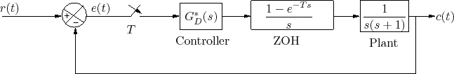
Consider the closed loop discrete control system as shown in Figure 1 .
 |
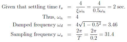
Design a digital controller such that the dominant closed loop poles have a damping ratio ![]() and settling time
and settling time ![]() sec for
sec for ![]() tolerance band. Take the sampling period as T = 0.2 sec. The dominant pole pair in continuous domain is
tolerance band. Take the sampling period as T = 0.2 sec. The dominant pole pair in continuous domain is ![]() where
where ![]() is the natural undamped frequency.
is the natural undamped frequency.