Module 4 : Voltage and Power Flow Control
Lecture 18 : Reactive Power Characteristics of Special Devices

HVDC Terminals

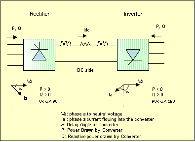
You must have learnt about various kinds of AC/DC converters in a Power Electronics Course. Line Commutated Converters (Thyristor Rectifier / Inverter Bridges) always absorb reactive power.The reactive power absorbed is substantial and can be as much as 30-40% of the power transmitted by the HVDC link. Usually shunt capacitors are connected to provide reactive power on the ac side of the converters.

If the thryistors are fired as soon as they get forward biased, then we say that the "delay angle" is zero. In such a case a thyristor bridge is identical to a three phase diode bridge. However, by delaying the firing, we can control the average voltage which appears on the DC side.

The delay angle associated with these controlled rectifiers results in lag of the fundamental of AC side current by approximately the same angle as the delay angle.

This is also true for inverter stations where the firing angle is greater than 90 degrees but less than 180 degrees. This is illustrated by the figure given on the right.


You may simulate HVDC link behavior using the MATLAB/SIMULINK file (HVDC.mdl).

HVDC systems of lower ratings may also be implemented using Voltage Source Converters. These converters use devices like Gate Turn off Thyristors which can be turned off by a gate signal. Unlike in a line commutated converter, the voltage on the DC side is unidirectional while current can flow in either direction on the DC side. These converters can absorb or supply reactive power independent of the real power flow in the line. As an exercise, read about AC/DC converters in a book on Power Electronics (e.g. Power Electronics by M.H.Rashid, Prentice Hall, 2002).