| |
| | |
|
Typical examples of intrusive technologies, their sensor types and installation
locations are shown in Fig. 1.
The first types of units (Fig. 1, Type 1) are
passive magnetic or magneto-meter sensors that are either permanently mounted
within holes in the road, or affixed to the road surface in some fashion.
The unit communicates to a nearby base station processing unit using either
wires buried in the road, or wireless communications.
The sensor has a circular or elliptically offset zone of detection
(i.e., the blue area).
Figure 1:
Typical intrusive detector configurations, Source: IMAGINE- Collection
Methods for Additional Data
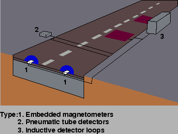 |
The second types of units (Fig. 1, Type 2) use
pneumatic tubes that are stretched across the carriageway and affixed at the
kerb side at both ends.
Such systems are only be deployed on a temporary basis, due to the fragile
nature of tubes, which are easily damaged or torn up by heavy or fast moving
vehicles.
The third type (Fig. 1, Type 3) are inductive
detector loops (IDL), consisting of coated wire coils buried in grooves cut in
the road surface, sealed over with bituminous filler.
A cable buried with the loop sends data to a roadside processing unit.
The zone of detection for inductive loop sensors depends on the cut shape of the
loop slots.
The zones depending on the overall sensitivity of system not correspond
precisely to the slot dimensions.
IDLs are a cheap and mature technology.
They are installed on both major roads and within urban areas, forming the
backbone detector network for most traffic control systems.
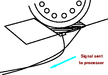
The fourth type of intrusive system is Weigh-In-Motion (WIM) shown in
Fig. 2, detectors that consist of a piezoelectric sensor
(e.g. `bending-plate' or fiber-optic) system laid in a channel across the road.
These systems are relatively rare and are used in specific locations for
enforcement or access control.
They are usually coupled with other systems, either intrusive or non-intrusive,
to provide additional cross-checks on collected data.
Figure 2:
Weigh-In-Motion Detector system, Source
 |
|
|
| | |
|
|
|