| |
| | |
|
Piezoelectric
Piezoelectric WIM systems contain one or more piezoelectric sensors that detect
a change in voltage caused by pressure exerted on the sensor by an axle and
thereby measure the axle s weight.
As a vehicle passes over the piezoelectric sensor, the system records the sensor
output voltage and calculates the dynamic load.
With bending plate systems, the dynamic load provides an estimate of static load
when the WIM system is properly calibrated.
The typical piezoelectric WIM system consists of at least one piezoelectric
sensor and two ILDs.
The piezoelectric sensor is placed in the travel lane perpendicular to the
travel direction.
The inductive loops are placed upstream and downstream of the piezoelectric
sensor.
The upstream loop detects vehicles and alerts the system to an approaching
vehicle.
The downstream loop provides data to determine vehicle speed and axle spacing
based on the time it takes the vehicle to traverse the distance between the
loops.
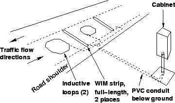
Fig. 1 shows a full-lane width piezoelectric WIM system
installation.
In this example, two piezoelectric sensors are utilized on either side of the
downstream loop.
Advantages
Typical piezoelectric WIM systems are among the least expensive systems in use
today in terms of initial capital costs and life cycle maintenance costs.
Piezoelectric WIM systems can be used at higher speed ranges (16 to 112 kmph)
than other WIM systems.
Piezoelectric WIM systems can be used to monitor up to four lanes.
Disadvantages
Typical piezoelectric systems are less accurate than load cell and bending plate
WIM systems.
Piezoelectric sensors for WIM systems must be replaced at least once every 3
years.
Figure 1:
WIM installation with full-length piezoelectric sensors Source: FHWA
vehicle detection manual
 |
|
|
| | |
|
|
|