A typical scan can cover a region of 1 m x 1m to 300 m x 300 m. Larger area scans take longer time. A sample image is shown in Figure 12.13. The limited sample area and longer scan time are some of the disadvantages of AFM. On the other hand, unlike SEM, the AFM can be done in normal atmospheric conditions, and even in liquids. For SEM analysis, the sample must be in ultra high vacuum. Recent advances allow handling samples in SEM at moderate vacuums, but it is still not possible to use samples in normal atmosphere or in liquids inside SEM.
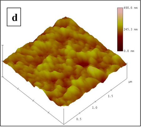
Figure 12.13. AFM Image of a cement brick (courtesy Dept. Met. Materials, IIT-Madras)
Constant force mode: When the force between the probe and surface is maintained constant using a control loop, the AFM is said to operate in “constant force” mode. If the probe is very close to the surface, and the force is repulsive, it is operating in contact mode. When the probe is a bit farther away and the force is attractive, it is operating in the noncontact mode. (i.e. the set point for non contact mode corresponds to attractive force regime). In contact mode, the topography information obtained is of high quality. However, if the surface is made of soft material, then it may be compressed during the measurement and the results obtained do not accurately reflect the actual surface in the natural state. Besides, in those cases, the probe may scratch (i.e. damage) the surface. If the surface is hard, the probe may be broken also.
In non-contact mode, the surface will not be damaged by the probe. The tip life is also longer. However, the resolution is not as good as that obtainable in the contact mode. A third possibility is to use the probe in oscillating mode. This is sometimes called tapping mode or intermittent contact mode or dynamic force mode. In this, the resonance frequency of the cantilever is measured and an AC voltage at that frequency is applied. Usually it will be in kHz range (i.e. thousands of oscillations per second). When the probe is not near any surface, it will oscillate at the resonant frequency. The AC signal of the reflected light will also be at the same frequency. When it is brought close to the surface, then the oscillations will be ‘damped’ by the surface. During one oscillation, the probe will be in the repulsive force regime for part of the time and will be in attractive force regime for the remaining time. By measuring the change in resonance frequency or the amplitude of resonance, the surface topography can be detected. In this mode, the damage to the surface is less, the probe life is better and at the same time, the resolution is better than that obtainable in pure non-contact mode.
Constant height mode: It is possible to operate the AFM in another mode called constant height mode. This is applicable only if the sample is very smooth. In this mode, the AFM tip is brought close to the surface and once it reaches a preset height above the surface, the X and Y piezo electric scanners move the sample surface and the tip position is recorded. The tip is not moved up or down and the control loop is not used. The advantage of this method is that the scan can be performed faster than in constant force mode. The disadvantage is that if the surface is rough, then the probe will crash. The image resolution is also a bit lower than available in constant force mode.
A partial list of suppliers of AFM (as of 2011) is Park systems (South Korea), Novascan (USA), Nanonics (USA), DME (Denmark), Digital Instruments (USA), JEOL (Japan), Nanosurf (Switzerland).
Ellipsometry: This method is often used to measure the thickness of very thin films, even down to 1 angstrom (0.1 nm). In this technique, the change in polarization of a light reflected from a sample is measured. In general, a light reflected at an angle (from the sample) is elliptically polarized. Normally a light source yields unpolarized light. The light is passed through a polarizer. Only a plane polarized light comes out the polarizer. It falls onto the sample and the reflected light will pass through another polarizer (called analyzer) and finally will be measured by a detector.
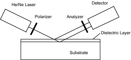
Figure 12.14. Key components of an ellipsometer
Ellipsometers measure the amplitude (Y)and phase difference (D). The film thickness and refractive index values are calculated from these values. Ellipsometry is an indirect method in the sense, the film thickness and refractive index values are not directly measured, nor are they directly calculated. Instead, a model of film thickness will be created and using a least square method, the thickness and refractive index which give the closest values of amplitude and phase difference matching with the experimental values will be taken as the film thickness.
The advantage of ellipsometry is that it is very quick, accurate and reproducible. By changing the angle of incidence, the data can be acquired in many angles (variable angle ellipsometry). Similarly by using light of different wavelengths, the data can be acquired at many wavelengths (spectroscopic ellipsometry). These allow for building robust models and facilitate accurately estimation of the film properties.
Thin film Reflectometry or Spectral reflectance: This is another techniques which uses light to measure the thickness and nature of a thin film. When a light falls on a thin film (which is coated on a planar reflective surface, then light is reflected from the top of the film as well as from the bottom of the film, as shown in Figure 12.14. The schematic 12.14 shows the presence of two films of thicknesses d1 and d2 and also with different refractive indices. The refractive index of a material is a complex number with a real part (n) and an imaginary part (k). The imaginary part (k) indicates the ability of the material to absorb the light. The refractive index is a function of wavelength of the light.
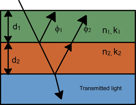
Figure 12.15 Spectral reflectance schematic of two transparent or semitransparent layers on top of a base.
The light reflected from various interfaces will interfere either constructively or destructively. The intensities of each reflected wave are not equal. Hence, even if the interference is destructive, the net intensity will only decrease but will not go to zero. If the interference is constructive, then the net intensity will increase. Whether a particular light will interfere destructively or constructively will depend on the wavelength of the light, the thickness of the films and the nature of the films (n and k values of the films).
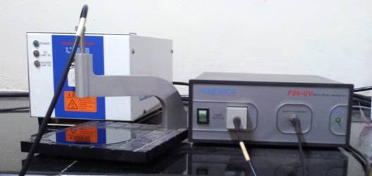
Figure 12.16. Spectral reflectance meter (Filmetrics F-20 UV). Courtesy Dept. Chem. Engg., IIT-Madras.
By using light source of many wavelengths and by measuring the intensity of the reflected wave (which is the net intensity after the interference from many interfaces), it is possible to calculate the n and k values of the film and also the thickness values (d). If the nature of the film is already known (i.e. n and k are known), it is easier to calculate the thickness accurately. The typical measurement time is a second and there are no moving parts in the instrument. This makes is very user friendly and trouble free. The cost is also relatively lower than that of an ellipsometer. On the other hand, when the film thickness is less than 10 nm, ellipsometer gives more reliable results. |