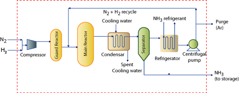
Figure 1.1: Process flow sheet for ammonia manufacture using Haber’s process.
1.6 Illustration of quickly learning process technology: Ammonia manufacture using Haber’s process (Figure 1.1)
| a) Reaction: The Haber process combines nitrogen from the air with hydrogen derived mainly from natural gas (methane) into ammonia. The reaction is reversible and the production of ammonia is exothermic. Nitrogen and hydrogen will not react under normal circumstances. Special conditions are required for them to react together at a decent rate forming a decent yield of ammonia. These conditions are T = 400°C; P = 200 atm; Iron catalyst with KOH promoter. b) Raw materials: H2 from synthesis gas, N2 from synthesis gas/air liquefaction process c) Process technology: Illustrated in Figure 1.1 d) Unit processes: Feed Guard Converter; Main Reactor e) Unit operations in the technology: Condensation/Gas Liquefaction; Separation; Refrigeration; Centrifugal Re-circulator f) Striking feature: Conversions are low (8 - 30 % per pass) and hence large recycle flow rates exist. g) Functional role of various processes |
| a. Feed guard converter: | ||
| » CO and CO2 conversion to CH4 and removal of traces of H2O, H2S, P and Arsenic. » These compounds could interfere with the main haber’s reaction as well as poison the catalyst. |
||
| b. Main reactor: | ||
» Cold reactants enter reactor from reactor bottom and outer periphery to absorb heat generated in the reversible reaction. » Carbon steel used for thick wall pressure vessel and internal tubes » Gas phase reaction at 500 – 550° C and 100 – 200 atms. » Pre-heated gas flows through the tube inside with porous iron catalyst at reaction conditions. » Catalyst removed from the converters is re-fused in an electric furnace. |
||
| c. Condenser: | ||
» Complete liquefaction not possible due to vapor liquid equilibrium between NH3 in vapor and liquid phases. » Cooling fluid: Chilled water » Incoming stream has: Gaseous NH3, un reacted N2 and H2, impurity gases like CO, CO2, CH4 » Product stream has: Liquefied NH3, Vapor phase NH3in equilibrium with liquid, non-condensable gases such as N2 and H2 » System pressure is high therefore NH3 bound to be present in higher concentrations in the vapor. |
||
| d. Separator: | ||
» Working principle: Density difference between vapor and liquid » Liquefied NH3 is separated from the un-reacted gases (NH3 still present in the vapors). |
||
| e. Refrigeration: | ||
» Why?: NH3 available in vapors needs to be condensed. Therefore, refrigeration is required for gaseous product emanating from the separator. » The condensed NH3 emanates at -15°C. » After refrigeration, the un-reacted N2 and H2 are recycled to the reactor. |
||
| f. Centrifugal pump: | ||
» A centrifugal pump adjusts the pressure of the stream from the separator to the pressure of the feed entering the reactor » A purge stream exists to facilitate the removal of constitutes such as Argon. |
||
| g. Striking feature: | ||
All units such as Condenser, Separator, Refrigerator operate at high pressure. This is because loosing pressure is not at all beneficial as the un-reacted reactants (corresponding to large quantity in this case due to low conversion in the reversible reaction) need to be supplied back to the reactor at the reactor inlet pressure conditions. |
||