·
Load due to wind acting in the upper portion of the vessel.
Puw = K1 K2 p2 h2 Do
Where,
Puw – total force due to wind load acting on the upper part above 20 m.
Do - outer diameter of the vessel including the insulation thickness
h2 – height of the upper part of the vessel above 20 m
K2 – coefficient depending upon the period of one cycle of vibration of the vessel
(K2 = 1, if period of vibration is 0.5 seconds or less; K2 = 2, if period exceeds 0.5 seconds)
Stress due to bending moment: Stress induced due to bending moment in the axial direction is determined from the following equations.
- (i) Mw = Pbw h1 /2 ; h1 ≤ 20m
(ii) Mw = Pbw h1 /2 + Puw (h1 + h2 /2 ) ; h1 ≤ 20m
Therefore, the bending stress due to wind load in the axial direction
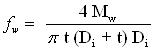 (6.15)
Where,
fw - longitudinal stress due to wind moment
Mw - bending moment due to wind load
Di – inner diameter of shell
t – corroded shell thickness
6. THE STRESS RESULTING FROM SEISMIC LOADS
The seismic load is assumed to be distributed in a triangular fashion, minimum at the base of the column and maximum at the top of the column. It is a vibrational load, it produces horizontal shear in self supported tall vertical vessel (Figure 6.4).
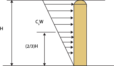
Figure 6.4a : Seismic forces on tall column
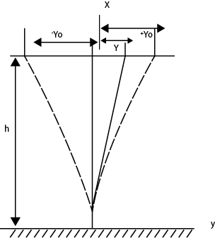
Figure 6.4b : Seismic forces on tall column