5. THE AXIAL STRESSES (TENSILE AND COMPRESSIVE) DUE TO WIND LOADS ON SELF SUPPORTING TALL VERTICLE VESSEL
The stress due to wind load may be calculated by treating the vessel as uniformly loaded cantilever beam. The wind loading is a function of wind velocity, air density and shape of tower.
The wind load on the vessel is given by
![]() (6.13)
(6.13)
Where,
CD = drag coefficient
ρ = density of air
Vw = wind velocity
A = projected area normal to the direction of wind
If wind velocity is known approximate wind pressure can be computed from the following simplified relationship.
![]() (6.14)
(6.14)
Pw = min wind pressure to be used form moment calculation, N/m2
Vw = max wind velocity experienced by the region under worst weather condition, km/h
Wind velocity varies with height. This can be observed from the figure shown below (Figure 6.3). The velocity of wind near the ground is less than that away from it. Therefore, to take into account this factor a variable wind force may be taken. It is recommended to calculate the wind load in two parts, because the wind pressure does not remain constant through the height of the tall vessel. Say for example in case of vessel taller than 20 m height, it is suggested that the wind load may be determined separately for the bottom part of the vessel having height equal to 20 m, and then for rest of the upper part.
Load due to wind acting in the bottom portion of the vessel.
Pbw = K1 K2 p1 h1 Do
Where,
Pbw– total force due to wind load acting on the bottom part of the vessel with height equal to or less than 20 m.
Do - outer diameter of the vessel including the insulation thickness
h1 – height of the bottom part of the vessel equal to or less than 20 m
K1 – coefficient depending upon the shape factor (i.e. 1.4 for flat plate; 0.7 for cylindrical surface)
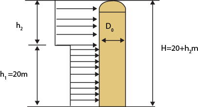
Figure 6.3 : Tall column subjected to wind pressure