·
Effective exchanger length (Leff ) = Lt + 2 x hi = 6.096 m + 2×0.1054 m
= 6.306 m
Thickness of head 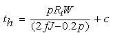 ; j =1 is taken for head design ; j =1 is taken for head design |
(2.2) |
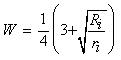 =1.77 for ri =0.06× Ri =1.77 for ri =0.06× Ri |
(2.3) |
th= 2.63 Including corrosion allowance 5.63 mm, use same thickness as for shell, i.e., 8 mm
iii. Channel cover thickness (refer section 2.3.3)
Channel cover material: carbon steel
| (2.4) |
Dc= Outside shell diameter=803.4 mm;C1= 0.3; p =3.88 kgf/cm2 (0.38 N/mm2 )
f = 10.26 kgf/mm2 (100.6 N/mm2 )
tcc = 8.5 mm; Use 12 mm including the corrosion allowance
iv. Tube sheet thickness (refer section 2.3.5)
The tube sheet thickness is calculated based on the bending and considering the design pressure only. It is assumed that shear does not control the design. Carbon steel is used for tube sheet material.
 |
(2.5) |
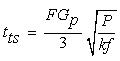
F=1 for fixed tube sheet; k=0.5 (square pitch)
tts =22.8 mm (satisfies the IS:4503 specification for 1΄΄outside diameter tube)
v. Impingement plate (refer section 2.3.6)
The density ( ρk) of the tube side fluid (kerosene) =0.8 g.cm3 (800 kg.m3 ); mass flow rate (mk) of kerosene =18.91 kg/s (150000 lb.h)
Kerosene velocity, 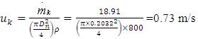
Where, nozzle diameter, Dn = 203.2 mm=0.2032 m
The impingement parameter, ρv2 = 0.8 x 0.732 = 0.426<<125
Therefore the impingement protection is not required.
vi. Nozzle thickness (tn)(refer section 2.3.7)
Use carbon steel for the nozzle (same material)
Considering diameter of nozzle ( Dn) to be 203.2 mm (8 inch) ( Table 2.3 ); j = 0.8
 |
(2.1) |
Use 6 mm thickness including the corrosion allowance.
The pressures at the entry point of both shell side and tube fluid are same. Therefore, the same nozzle specification can be used for tube side fluid also.