3. SOLVED EXAMPLE
Part 2: Mechanical design
(Part 1: Thermal design calculation is given in module #1)
The process design of shell and tube for single phase heat transfer solved in module #1 is continued for the mechanical design.
The minimum information required for the mechanical design of some important components of shell and tube exchanger is summarized below:
- a. Shell side and tube side passes: 1 shell pass and 6 tube passes.
b. Number, type, size, and layout of tubes: Number of tubes 318; tube length 20΄ (6.096 m as per IS: 4503-1967 and IS:2844-1964 standards); tube OD 1΄΄ (25.4 mm); tube ID: 0.834΄΄ (21.2 mm); square pitch ![]() ; fixed tube sheet.
; fixed tube sheet.
c. Shell diameter and head: Shell ID 31΄ (787.4 mm); torispherical head is selected;carbon steel for both shell and head.
d. Corrosion allowance: Corrosion allowance of 3 mm for carbon steel is taken as per IS:4503 for the service in the petroleum industries.
e. Design temperature and pressure: design temperature 1.1×160=176°F (80°C) (10% greater than the highest process fluid temperature is taken); design pressure 0.38 N/mm2 (55 psia) (10% higher than the inlet pressure of both the streams).
f. Permissible stress, f =100.6 N/mm2 for carbon steel.
i. Shell thickness calculation (refer section 2.3.1)
 |
(2.1) |
Including corrosion allowance 6.72 mm, use 8 mm thickness
(This value is in accordance to IS:4503 corresponding to the shell diameter)
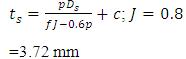
ii. Torispherical head (refer section 2.3.2)
Crown radius, Ri = 787.4 mm (crown radius, Ri = Ds is considered)
Knuckle radius ri =0.06 of Ri = 47.24 mm (knuckle radius ri =6% of Ds is taken)
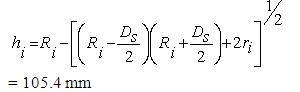
Inside depth of the head ( hi) can be calculated as: