The effective thickness of the tube sheets also can be calculated by the method given in Appendix E of IS:4503, by trial and error approach. IS:4503 specifies that the minimum tube sheet thickness should be between 6 and 25.4 mm based on the outside tube diameter.
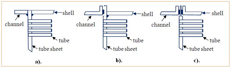
Figure 2.2. Tube sheet connections: a) Integral construction on both sides, b). one side integral construction and other side gasketed construction, c). both side gasketed construction.
2.3.6. Impingement plates or baffles
Impingement plates are fixed on the tube side between the tube bundle and inlet nozzle to deflect the liquid or vapor-liquid mixture to protect the tubes from erosion.
According to the IS:4503, the protection against impingement may not be required for the services involving non-corrosive, non-abrasive, single phase fluids having entrance line values of ρu2<125, where u is the linear velocity of the fluid in m/s and ρ is the density in g/cm3. In all other cases, the tube bundle at the entrance against impinging fluids should be protected. Usually a metal plate about ¼ inch (6 mm) thick is used as the impingement plate.
2.3.7. Nozzles and branch pipes
The wall thickness of nozzles and other connections shall be not less than that defined for the applicable loadings, namely, pressure temperature, bending and static loads (IS:4503). But in no case, the wall thickness of ferrous piping, excluding the corrosion allowance shall be less than (0.04doc +2.5) mm, where doc is the outside diameter of the connection. The typical nozzle size with shell ID is provided in Table 2.3 .
Table 2.3. Nozzle size with shell ID.
Shell ID, inch |
Nozzle ID, inch |
<12 |
2 |
12 to 17.25 |
3 |
19.25 to 21.25 |
4 |
23.23 to 29 |
6 |
31-38 |
8 |
>39 |
10 |