2.3 Design components
The major mechanical design components of shell and tube heat exchangers are: shell andtube-sheet thickness, shell cover, flanges, nozzles, gaskets, stress calculations and design of supports.
2.3.1. Shell diameter and thickness
The nominal diameter (outside diameter in millimeters rounded is to the nearest integer) of the heat exchanger is specified in IS: 2844-1964 in case of shells manufactured from flat sheet. The following diameters (in mm) should be preferably used in the case of cylindrical pipe shell: 159, 219, 267, 324, 368, 419, 457, 508, 558.8, 609.6, 660.4, 711.2,762, 812.8, 863.6, 914.4 and 1016.
The shell thickness (ts) can be calculated from the equation below based on the maximum allowable stress and corrected for joint efficiency [2]:
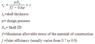 |
(2.1) |
The minimum shell thicknesses should be decided in compliance with the nominal shell diameter including the corrosion allowance as specified by IS: 4503. Usually the minimum shell thicknesses are in order for various materials for the same service: Cast iron >Carbon steel ≥ Al and Al-alloys (up to 700°C) >Cu and Cu-alloys ≥ Ni ≥ Austenitic stainless steel =Monel inconel.
2.3.2. Shell cover
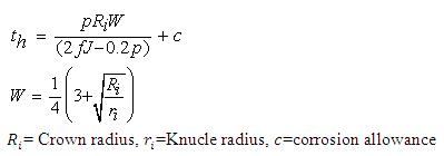
There are different types shell covers used in shell and tube heat exchangers: flat, torispherical, hemispherical, conical and ellipsoidal. Out of various types of head covers, torispherical head is the most widely used in chemical industries for operating pressure up to 200 psi. The thickness of formed head is smaller than the flat for the same service [2]. Accordingthe IS: 4503, the minimum thickness of the shell cover should be at least equal to the thickness of the shell.
The required thickness of a torispherical head (th) can be determined by:
 |
|
(2.3) |
2.3.3. Channel coversdiameter and thickness
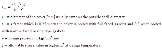
The outside diameter of the channel shall be the same as that of the shell. The thickness of the channel shall be greater of the two values: (i) shell thickness or (ii) thickness calculated on the basis of the design shown below pressure.
The effective channel cover thickness (tcc in mm) is calculated from the formula (IS:4503 section 15.6.1) [1]:
 |
(2.4) |