·
Table 1.2 . Common tube layouts.
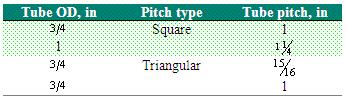
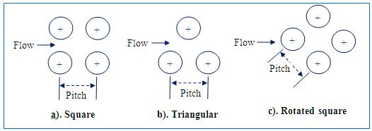
Figure 1.5 . Heat exchanger tube-layouts.
1.2.5. Tube sheet
The tubes are fixed with tube sheet that form the barrier between the tube and shell fluids. The tubes can be fixed with the tube sheet using ferrule and a soft metal packing ring. The tubes are attached to tube sheet with two or more grooves in the tube sheet wall by ‘tube rolling'. The tube metal is forced to move into the grooves forming an excellent tight seal. This is the most common type of fixing arrangement in large industrial exchangers. The tube sheet thickness should be greater than the tube outside diameter to make a good seal. The recommended standards (IS:4503 or TEMA) should be followed to select the minimum tube sheet thickness.
1.2.6. Baffles
Baffles are used to increase the fluid velocity by diverting the flow across the tube bundle to obtain higher transfer co-efficient. The distance between adjacent baffles is called baffle-spacing. The baffle spacing of 0.2 to 1 times of the inside shell diameter is commonly used. Baffles are held in positioned by means of baffle spacers. Closer baffle spacing gives greater transfer co-efficient by inducing higher turbulence. The pressure drop is more with closer baffle spacing. The various types of baffles are shown in Figure 1.6 . In case of cut-segmental baffle, a segment (called baffle cut) is removed to form the baffle expressed as a percentage of the baffle diameter. Baffle cuts from 15 to 45% are normally used. A baffle cut of 20 to 25% provide a good heat-transfer with the reasonable pressure drop. The % cut for segmental baffle refers to the cut away height from its diameter. Figure 1.6 also shows two other types of baffles.