An AFM has a pointed probe attached to a rectangular base called a cantilever. The positioning of the cantilever with respect to the specimen is achieved by the piezoelectric elements, called scanners. The piezoelectric element can be connected either to the cantilever or the specimen stage. In the initial AFMs, the piezoelectric element was a piezoelectric tube (Figure 19.3A) that can be allowed to position the cantilever in the three dimensional space. As the X, Y, and Z scanners in a piezoelectric tube are coupled, there is always some crosstalk between the scanners. For example, if you command the probe to be shifted by x units in the X-direction, there is generally a significant displacement in the Y and Z directions. Any such movement of the cantilever in Z-direction is undesired and adds the errors to the data. Modern AFM instruments therefore use an alternative set of scanners wherein Z-scanner is separated from the X-Y scanner (Figure 19.3B).
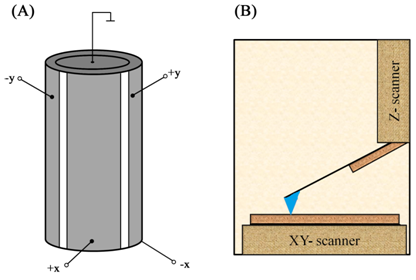
Figure 19.3 Piezoelectric scanners used in AFM: A piezoelectric tube (A) and a scanner having decoupled X-Y and Z piezoelectric elements (B).
A laser beam is focused on the cantilever that has a highly reflective surface. The laser beam reflected off the cantilever is focused on a position sensitive photodiode quadrant. The cantilever is scanned over the sample surface in a raster pattern. Any deflection in the cantilever as a result of sample interaction causes displacement in the laser spot on the photodiode; this displacement signal is analyzed to calculate the deflection in the cantilever. Imaging can be performed in either constant-force mode (distance between the tip and the specimen is allowed to change) or constant-height mode (force between the tip and the specimen is allowed to change).