Confocal Laser Scanning Microscope (CLSM)
A schematic diagram of a confocal laser scanning microscope is shown in figure 16.2A. Let us see how exactly a CLSM works:
- Light source and illumination: Light sources used in confocal microscopes are lasers . The microscope works in epi-illumination mode. The laser beam is spread by a diverging lens so as to fill the back aperture of the objective lens which functions as condenser as well. The expanded laser light is reflected by the dichroic mirror on the objective that focuses the light as an intense diffraction-limited spot on the sample. The fluorescence from the illuminated spot is collected by the objective and sent to the eyepiece/camera/detector through a pinhole aperture.
- Pinhole aperture: The fluorescence light emitted by the illuminated sample is focused as the confocal point at the pinhole. Any light coming from below or above the focal plane is blocked by the pinhole plate.
- Raster scanning: As the fluorescence is detected from a diffraction limited spot, the focused laser spot is scanned over the sample in a raster fashion collecting light from the entire focal plane (Figure 16.3A). The laser spot is scanned over the sample by changing the direction of the incident radiation as shown in Figure 16.3B. As the position of the illuminating spot changes, the pinhole moves so as to be confocal with the illuminated spot of the same focal plane.
- Emission filter: The light that passes through the pinhole is filtered by the emission filter before it reaches the detector.
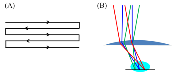
Figure 16.3 A raster scan (A); raster scanning by changing the direction of the exciting radiation (B).
Optical sectioning and three-dimensional reconstruction
A confocal microscope records the intensity of all the diffraction-limited spots in a focal plane, essentially providing an optical section of the sample. This can be understood as a plot of intensity in a two coordinate system. Obtaining such plots for closely spaced focal planes allows three-dimensional reconstruction of the sample by stacking the images (Figure 16.4).
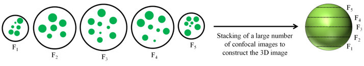 Figure 16.4 A diagram showing images recorded from five different focal planes and three-dimensional reconstruction of the object by stacking a large number of images from different focal planes.