A Pitot probe is a simple tube with a pressure tap at the stagnation point where the flow comes to rest and thus the pressure measured at this point is the stagnation pressure (Fig. 7.2.2-a). The Pitot-static probe consists of a slender double-tube aligned with the flow and connected to a differential pressure measuring device such as manometer (Fig. 7.2.2-b). The inner tube is fully open to the flow at the nose and thus measures the stagnation pressure (point ‘1') while the outer tube is sealed at the nose, but has the holes on the circumference of the outer wall for measuring the static pressure (point ‘2'). Neglecting frictional effects in Fig. 7.2.2(c), Bernoulli's equation can be applied for the point ‘1 and 2' to obtain the average flow velocity as given by Eq. (7.2.1). This equation is also known as Pitot formula . The volume flow rate can be obtained by multiplying the cross-sectional area to this velocity.
The Pitot-static probe is a simple, inexpensive and highly reliable device because it has no moving parts. Moreover, this device can be used for velocity/flow rate measurements for liquids as well as gases. Referring to Eq. (7.2.1), the dynamic pressure (i.e. difference between stagnation and static pressure) is proportional to the density of the fluid and square of the flow velocity. When this device is used for gases, it is expected that velocity is relatively high to create a noticeable dynamic pressure because gases have low densities.
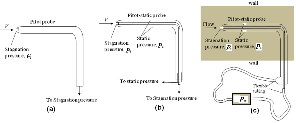
Fig. 7.2.2: (a) Pitot probe; (b) Pitot-static probe; (c) Measuring flow velocities with a Pitot-static probe.
Obstruction Flow meters
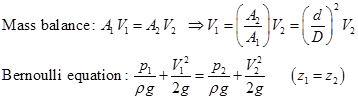
The flow rate through a pipe can be determined by constricting the flow and measuring the decrease in pressure due to increase in velocity at the constriction. In order to illustrate this fact, consider an incompressible steady flow of fluid in a horizontal pipe area ![]() and diameter (D) which is constricted to a flow area
and diameter (D) which is constricted to a flow area ![]() and diameter (d) at certain location (Fig. 7.2.3). The mass balance and Bernoulli equation can be applied between a location before the constriction (point ‘1') and at the constriction site (point ‘2').
and diameter (d) at certain location (Fig. 7.2.3). The mass balance and Bernoulli equation can be applied between a location before the constriction (point ‘1') and at the constriction site (point ‘2').
 |
(7.2.2) |
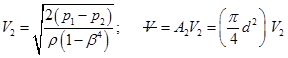
Combining both the equations and solving for ![]() one can obtain the expression for velocity and flow rate
one can obtain the expression for velocity and flow rate ![]() at the constriction location.
at the constriction location.
 |
(7.2.3) |
where, ![]() and
and ![]() are the pressure and velocities at points ‘1 and 2', respectively and
are the pressure and velocities at points ‘1 and 2', respectively and ![]() is the diameter ratio. It is noticed from Eq. (7.2.3) that the flow rate through a pipe can be determined by constricting the flow and measuring the decrease in pressure due to increase in velocity at the constriction site. The devices based on this principle is known as obstruction flow meters and widely used to measure flow rates for gases and liquids. Depending on nature of constriction, the obstruction flow meters are classified as orifice, nozzles and venturimeter as shown in Fig. 7.2.4.
is the diameter ratio. It is noticed from Eq. (7.2.3) that the flow rate through a pipe can be determined by constricting the flow and measuring the decrease in pressure due to increase in velocity at the constriction site. The devices based on this principle is known as obstruction flow meters and widely used to measure flow rates for gases and liquids. Depending on nature of constriction, the obstruction flow meters are classified as orifice, nozzles and venturimeter as shown in Fig. 7.2.4.
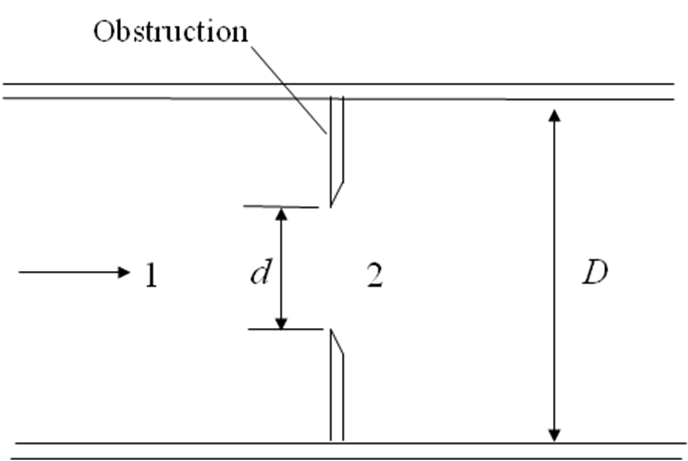
Fig. 7.2.3: Flow through a constriction in a pipe.
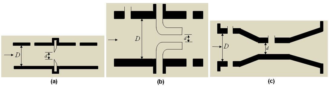
Fig. 7.2.4: Classification of obstruction flow meters: (a) orifice; (b) nozzle; (c) venturimeter.