In active region,
![]() for silicon BJT, and
for silicon BJT, and
![]() for Germanium BJT.
for Germanium BJT.
In saturated region,
![]() .
.
Common realizations of BJT are shown in 10.1
In active region:
Three configurations in the active region are shown in figure
10.2. For active region, the specified biasing condition is
satisfied.
When transistor is used for switching purposes, it works in either cut-off or saturation mode.
In active region, the base and collector currents satisfy the
condition
![]() (DC Current gain. Ratio of absolute
values).
(DC Current gain. Ratio of absolute
values). ![]() is a constant for a particular transistor, which varies from
is a constant for a particular transistor, which varies from ![]() to
to ![]() for
different transistors. Note that this condition does NOT hold for saturation
and cut-off operations of the BJT.
for
different transistors. Note that this condition does NOT hold for saturation
and cut-off operations of the BJT.
Now we address the problem of circuit design, in which we find appropriate values of resistances and voltages in figure 10.3 to ensure BJT in active region. The problem assumes importance as many transistor applications are those in which it is in active region.
In cut-off, ![]() , as
, as
![]() . If
. If
![]() becomes
less than
becomes
less than ![]() , the transistor is in saturation. We need to ensure
that the BJT is not in these states.
, the transistor is in saturation. We need to ensure
that the BJT is not in these states.
In active region, as
![]() ,
,
 |
|||
Let
![]() . Then,
. Then,
![]() . Suppose
the BJT has
. Suppose
the BJT has ![]() .
.
![]() .
.
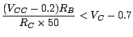
Also, we need to ensure
![]() , so that BJT is not in
saturation. In the limiting case,
, so that BJT is not in
saturation. In the limiting case,
![]() , just when the BJT is
entering saturation from active region. (In active region,
, just when the BJT is
entering saturation from active region. (In active region,
![]() ).
).
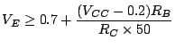
Thus,
![]() . That is,
. That is,
![]() for ensuring BJT in active
region.
for ensuring BJT in active
region.
Suppose we increase ![]() to
to
![]() . Then,
. Then,
![]() . Thus, the current gain
. Thus, the current gain
![]() .
.
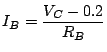
Cut off and saturation are used in switching application. For the circuit shown in figure 10.4, we find conditions for operating BJT as a switch.
When ![]() ,
, ![]() ,
, ![]() , and
, and
![]() , since BJT is in cut-off.
, since BJT is in cut-off.
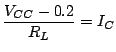
Now find ![]() such that the BJT is in saturation.
such that the BJT is in saturation.
 |
|||
 |
|||
 |
|||
 |
|||
 |
|||
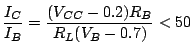
| Thus, we get: |
Thus, for
![]() , the BJT is in active region.
, the BJT is in active region.
Two different biasing strategies are shown in figure 10.6 and 10.7.
![\includegraphics[width=5.0in]{lec13figs/1.eps}](img716.png)
![\includegraphics[width=3.0in]{lec13figs/2.eps}](img717.png)
![\includegraphics[width=3.0in]{lec13figs/3.eps}](img722.png)
![\includegraphics[width=2.0in]{lec13figs/4.eps}](img742.png)
![\includegraphics[width=3.0in]{lec13figs/6.eps}](img754.png)
![\includegraphics[width=2.0in]{lec13figs/7.eps}](img755.png)
![\includegraphics[width=2.0in]{lec13figs/8.eps}](img756.png)