We have two independent variables here ![]() and
and ![]() . For different value of
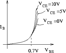
. For different value of ![]() , the input characteristics
, the input characteristics ![]() as a function of
as a function of ![]() is as follows.
is as follows.
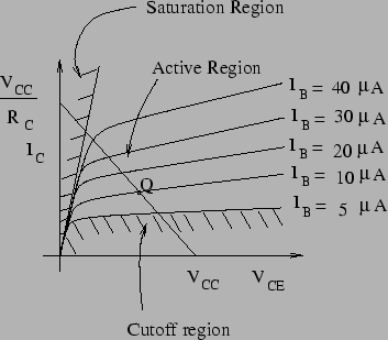
Similarly, for different values of ![]() , the
, the ![]() vs.
vs. ![]() characteristic is shown below. The line passing through
characteristic is shown below. The line passing through
![]() and
and
![]() is known as the load line and its intersection with the
is known as the load line and its intersection with the
![]() curve determines the quiscent point or operating point Q. Note that in the active region,
curve determines the quiscent point or operating point Q. Note that in the active region, ![]() is almost independent of
is almost independent of ![]() (i.e. nearly constant) and depends mostly on
(i.e. nearly constant) and depends mostly on ![]() . The ratio
. The ratio
![]() is a constant for the active region and is known as
is a constant for the active region and is known as ![]() .
.
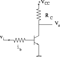
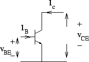
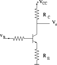
In the common emitter circuit shown above,
 |
For the cutoff region, ![]() and
and
![]() V.
V.
In the saturation region,
![]() V and
V and
![]() .
.
We will denote the operating point by ![]() and
and ![]() .
.
The fact that in the active region, variations in ![]() result in proportional varitions in
result in proportional varitions in ![]() and hence
and hence ![]() forms thefundamental principle of amplifier. For the trabsistor to remain in the active region throughout this variation, variations in
forms thefundamental principle of amplifier. For the trabsistor to remain in the active region throughout this variation, variations in ![]() should be maximum
should be maximum ![]() A.
A.
In the CE configuration above, with the change in temperature, ![]() changes and hence, so does Q.
changes and hence, so does Q. ![]() is an increasing function of T and therefore as T increases,
is an increasing function of T and therefore as T increases, ![]() increases causing further heating of the transistor and thereby further increasing
increases causing further heating of the transistor and thereby further increasing ![]() . This is known as thermal runaway. To avoid this, we stabilize the circuit my introducing an emitter resistance.
. This is known as thermal runaway. To avoid this, we stabilize the circuit my introducing an emitter resistance.
Now, as T increases, ![]() increases and so does
increases and so does ![]() . This increases
. This increases ![]() and therefore reduces
and therefore reduces ![]() as the base voltage increases. This decrease in
as the base voltage increases. This decrease in ![]() resluts in decrease of
resluts in decrease of ![]() , thereby compensating the effect of temperature and stablization of the operating point.
, thereby compensating the effect of temperature and stablization of the operating point.