next up previous contents
Next: Sinusoidal Steady State Response Up: Introduction to Electronics Previous: Transient response of RL   Contents

R-C Circuits

An RC circuit is shown in fig.7.1. Since, in practical circuits, power is always switched on at certain time, a switch is provided here.
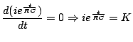
 This switch closes at time $ t=0$.

Figure 7.1: An RC Circuit
\includegraphics[width=2.0in]{lec6figs/4.eps}

We are interested in finding how voltage across capacitor $ v_c (t)$ changes with time? We can also assume that voltage across the capacitor is zero $ t < 0$. 
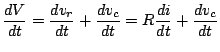
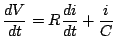
Using Kirchoff's voltage law across the only loop in circuit we can find the equation relating $ v_c$, $ v_r$ and $ V$.

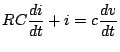
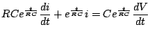
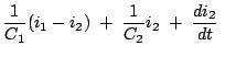
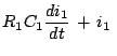
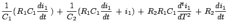
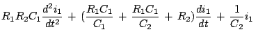
Using the characterstic equations of capacitors, resistors i.e.,

$\displaystyle C\frac{dv}{dt}=i$    
$\displaystyle iR=v_r$    

and using KVL

$\displaystyle v_r + v_c=V$    
$\displaystyle \frac{dV}{dt}=\frac{dv_r}{dt}+\frac{dv_c}{dt}=R\frac{di}{dt}+\frac{dv_c}{dt}$    
$\displaystyle \frac{dV}{dt}=R\frac{di}{dt}+\frac{i}{C}$ for $\displaystyle t>0$    
for $\displaystyle t<0$   , $\displaystyle i(t)=0$    
$\displaystyle RC\frac{di}{dt}+i=c\frac{dv}{dt}$    
$\displaystyle RC e^{\frac{t}{RC}}\frac{di}{dt}+e^{\frac{t}{RC}}i=C e^{\frac{t}{RC}}\frac{dV}{dt}$    
For $\displaystyle t\geq 0$   , $\displaystyle V=$constant    
$\displaystyle \frac{dV}{dt}=0$    
$\displaystyle \frac{d(i e^{\frac{t}{RC}})}{dt}=0\Rightarrow ie^{\frac{t}{RC}}=K$    
Thus, $\displaystyle i(t)=Ke^{- \frac{t}{RC}}$   ; here $\displaystyle K$ is constant    

At $ t=0$, capacitor voltage will be 0. Hence $ i(t=0)=\frac{V}{R}e^{-\frac{t}{RC}}$

Alternatively,

$\displaystyle V_c=V-iR$    
$\displaystyle V_c=V-RK e^{- \frac{t}{RC}}$    
at $\displaystyle t=0, v_c=0$    
Thus, $\displaystyle K=\frac{V}{R}$    

Thus,

$\displaystyle V_c=V(1- e^{-\frac{t}{RC}})$ (7.1)

The curves showing $ v_c (t)$ and $ i(t)$ are shown in the figures 7.2 and 7.3.

Figure 7.2: i vs t
\includegraphics[width=3.0in]{lec6figs/2.eps}
Figure 7.3: $ V_c$ vs t
\includegraphics[width=3.0in]{lec6figs/3.eps}
These show the exponetially decaying (growth) nature of current (voltage across capacitor).

Consider the figure shown in 7.1. The switch is closed at $ t=0$.

Now,

$\displaystyle V=v_c+iR$    
$\displaystyle V=\frac{1}{C}\int_{-\infty}^{t}i\;dt+iR$    
$\displaystyle \frac{dV}{dt}=\frac{1}{C}i+R\frac{di}{dt}$    
$\displaystyle e^{\frac{t}{RC}}\frac{dv}{dt}=e^{\frac{t}{RC}}\frac{i}{C}+Re^{\frac{t}{RC}}\frac{di}{dt}$    
$\displaystyle 0=e^{\frac{t}{RC}}\frac{dv}{dt}=\frac{d(Rie^{\frac{t}{RC}})}{dt}$    
$\displaystyle Integrating\;with\;proper\;limits,\;we\;get\;i(t)=i_0e^{-\frac{t}{RC}}$    
$\displaystyle and\;\;v_C(t)=V-Ri(t)=V-Ri_0e^{-\frac{t}{RC}}$    
$\displaystyle v_C(t)=V-Ri_0$    
$\displaystyle Ri_0=V-V_c(0)$    
$\displaystyle \Rightarrow v_C(t)=V_F-(V_F-v_c(0))e^{-\frac{t}{RC}}$    

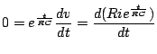
For RC circuit with source voltage zero, and an initial capacitor voltage of $ v(0)$, this expression reduces to $ v(t)=v(0)e^{-\frac{t}{RC}}$.

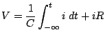
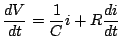
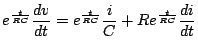
For constant current charging of a capacitor, as shown in 7.4, the analysis:

Figure 7.4: Constant current excitation of a capacitor
\includegraphics[width=3.0in]{lec6figs/5.eps}

$\displaystyle C\frac{dv}{dt}=i=I$ (7.2)
$\displaystyle \Rightarrow V=\frac{I}{C}t$ (7.3)

That is, voltage varies linearly with time on constant current charging.
Figure 7.5:
\includegraphics[width=3.0in]{lec6figs/7.eps}

$\displaystyle R_1i_1 + \frac{1}{C_1}\int_0^t (i_1-i_2)dt\;$ $\displaystyle =$ $\displaystyle \;0$  
$\displaystyle \frac{1}{C_1}\int_0^t(i_2-i_1)dt\;+\;i_2R_2\;+\;\frac{1}{C_2}\;$ $\displaystyle =$ $\displaystyle \;0$  
$\displaystyle R_1\frac{di_1}{dt}\;+\frac{1}{C_2}(i_i)-\frac{1}{C_1}i_2\;$ $\displaystyle =$ $\displaystyle \;0$  
$\displaystyle \frac{1}{C_1}(i_1-i_2)\;+\;\frac{1}{C_2}i_2\;+\;\frac{di_2}{dt}\;$ $\displaystyle =$ $\displaystyle \;0$  
$\displaystyle \mathrm{From the above, we have}$      
$\displaystyle R_1C_1\frac{di_1}{dt} + i_1\;$ $\displaystyle =$ $\displaystyle i_2$  
$\displaystyle \frac{1}{C_1}( R_1C_1\frac{di_1}{dt} ) + \frac{1}{C_2}(R_1C_1\frac{di_1}{dt} + i_1) + R_2R_1C_1\frac{d^ti_1}{dT^2} + R_2\frac{di_1}{dt}\;$ $\displaystyle =$ 0  
$\displaystyle R_1R_2C_1\frac{d^2i_1}{dt^2} + (\frac{R_1C_1}{C_1} + \frac{R_1C_1}{C_2} + R_2)\frac{di_1}{dt} + \frac{1}{C_2}i_1\;$ $\displaystyle =$ $\displaystyle \;0$  

Now consider the circuit shown in figure 7.6
Figure 7.6:
\includegraphics[width=3.0in]{lec6figs/8.eps}

The switch is turned off at $ t = 5$ sec. There is no charge on the capacitor initially. Therefore, after $ t = 0$ and before $ t = 5$, the circuit is equivalent to figure 7.7

Figure 7.7:
\includegraphics[width=3.0in]{lec6figs/9.eps}

Taking thevenin equivalent in the direction of the arrow leads to figure 7.8

Figure 7.8:
\includegraphics[width=3.0in]{lec6figs/10.eps}

Therefore ,

$\displaystyle V_F =5\mathrm{ V}\quad,\quad RC\;$ $\displaystyle =$ $\displaystyle \;2.5\times10$  
  $\displaystyle =$ $\displaystyle 25$  

For $ v_c(r\mathrm{sec})$, we have the following equation
$\displaystyle \Rightarrow\qquad v_c(5\mathrm{sec})\;$ $\displaystyle =$ $\displaystyle 5 + (0 - 5)e^{-\frac{t}{25}}$  
  $\displaystyle =$ $\displaystyle \;5(1-e^{-\frac{5}{25}})$  
  $\displaystyle =$ $\displaystyle \;0.906 \mathrm{ volts}$  

After $ t = 5 \mathrm{sec}$, the switch is once again thrown open and the equivalent circuit is shown in figure 7.9

Figure 7.9:
\includegraphics[width=3.0in]{lec6figs/11.eps}

Now,

$\displaystyle v_F\;\;=\;\;0\qquad,\qquad v_I\;\;=\;\;0.906
$


$\displaystyle v_c(t)\;$ $\displaystyle =$ $\displaystyle \;0 + (0.906-0) e^{-\frac{t-5}{30}}$  
  $\displaystyle =$ $\displaystyle \;0.906 e^{-\frac{t-5}{30}}$  

Therefore,
$\displaystyle v_c(t)\;$ $\displaystyle =$ $\displaystyle \;\;5(1-e^{-\frac{t}{25}})\qquad0<t\leq 5$  
    $\displaystyle \;\;0.906e^{-\frac{t-5}{30}}$  

The graph of $ v_c (t)$ with time is shown in figure 7.10

Figure 7.10:
\includegraphics[width=3.0in]{lec6figs/12.eps}


next up previous contents
Next: Sinusoidal Steady State Response Up: Introduction to Electronics Previous: Transient response of RL   Contents
ynsingh 2007-07-25