Clippers:
Clipping circuits are used to select that portion of the input wave which lies above or below some reference level. Some of the clipper circuits are discussed here. The transfer characteristic (vo vs vi) and the output voltage waveform for a given input voltage are also discussed.
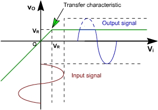
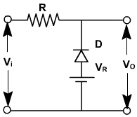
Clipper Circuit 1:
The circuit shown in fig. 3, clips the input signal above a reference voltage (VR).
In this clipper circuit,
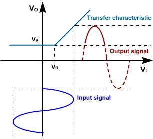
If vi < VR, diode is reversed biased and does not conduct. Therefore, vo = vi
and, if vi > VR, diode is forward biased and thus, vo= VR.
The transfer characteristic of the clippers is shown in fig. 4.
Fig. 3
Fig. 4
Clipper Circuit 2:
The clipper circuit shown in fig. 5 clips the input signal below reference voltage VR.
In this clipper circuit,
If vi > VR, diode is reverse biased. vo = vi
and, If vi < VR, diode is forward biased. vo = VR
The transfer characteristic of the circuit is shown in fig. 6.
Fig. 5
Fig. 6
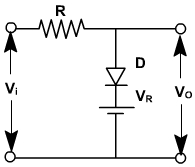
Clipper Circuit 3:
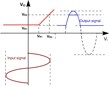
To clip the input signal between two independent levels (VR1< VR2 ), the clipper circuit is shown in fig. 7.
The diodes D1 & D2 are assumed ideal diodes.
For this clipper circuit, when vi ≤ VR1, vo=VR1
and, vi ≥ VR2, vo= VR2and, VR1 < vi < VR2 vo = vi
The transfer characteristic of the clipper is shown in fig. 8.
Fig. 7
Fig. 8