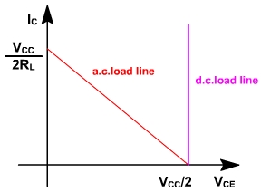
Since there is no dc resistance in the collector or emitter circuits, the dc saturation current is infinite. The dc load line is vertical as shown in fig. 6. The most difficult thing is setting up a stable Q-point at cut off. Any significant increase in V BE with temperature can move the Q-point up the dc load line to dangerously high currents. Ac load line is given by
I C(sat) = I CQ + (V CEQ / r E )
V CE (cut off) = V CEQ + I CQ r E
I CQ = 0; V CEQ = V CC / 2
i.e. I C(sat) = V CC / 2RL ( i.e. rE = R L )
V CE (cut off) = V CC / 2.
Fig. 6
When either transistor is conducting, that transistor's operating point swings along the ac load line and the operating point of the other transistor remains at cut off. The voltage swing of the conducting transistor can go from cut off to saturation. In the next half cycle, the other transistor does the same thing.
Therefore, PP = VCC
Voltage gain of loaded amplifier:
AV= R L / (R L + r'e )
Z in (base) » b (RL + r'e )
Z out = r'e + (r B ) / b
A P =A V * Ai
Without signal the capacitor charges up to VCC / 2 relative to ground.
In the positive half cycle of input voltage, the upper transistor conducts and the lower one cut off. The upper transistor acts like an ordinary emitter follower, so that the output voltage approximately equals the input voltage. The current flow through RL is such as direct as to make output positive.
In the negative half cycle of input voltage, the upper transistor cuts off and the lower transistor conducts. The lower transistor acts like an ordinary emitter follower and produces a load voltage approximately equal to the input voltage (i.e. negative output. Since Q, is off, no current can flow from VCC through Q, but capacitor acts like a battery source and discharges).
During either half cycle, the source sees a high input impedence looking into either base and the load sees a low output impedence.