Example-2 (Emitter-Resistor Amplifier Design)
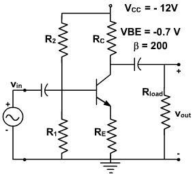
Design an emitter-resistor amplifier as shown in fig. 2 to drive a 2 KΩ load using a pnp silicon transistor, VCC = -24V, β = 200, Av = -10, and VBE = -0.7 V. Determine all element values and calculate Ai, Rin, ICQ and the maximum undistorted symmetrical output voltage swing for three values of RC as given below:
- RC = Rload
- RC = 0.1 Rload
- RC = 10 Rload
Fig. 2
Solution:
(a) RC = Rload
We use the various equations derived in previous lecture in order to derive the parameters of the circuit.
From the voltage gain, we can solve for R'E.
So R'E = re + RE = 100 Ω
We can find the quiescent value of the collector current IC form the collector-emitter loop using the equation for the condition of maximum output swing.
Therefore,
This is small enough that we shall ignore it to find that RE = 100 Ω. Since we now know β and RE. We can use the design guideline.
RB = 0.1 β RE = 2 k Ω
As designed earlier, the biasing circuitry can be designed in the same manner and given by
VBB = -1.52 V
R1 = 2.14 K Ω
R2 = 3.6 K Ω
The maximum undistorted symmetrical peak to peak output swing is then
Vout (P-P) = 1.8 ICQ (Rload || RC ) = 13.5 V
Thus current gain Ai = -9.1
and input impedance Rin = 1.82 K Ω
(b) RC = 0.1 Rload
we repeat the steps of parts (a) to find
(C) RC =10 Rload
Once again, we follow the steps of part (a) to find
We now compare the results obtained Table-I for the purpose of making the best choice for RC.
Table - 1 Comparsion for the three selections of RC
It indicates that of the three given ratios of RC to Rload, RC = Rload has the most desirable performance in the CE amplifier stage.
It can be used as a guide to develop a reasonable designs. In most cases, this choice will provide performance that meets specifications. In some applications, it may be necessary to do additional analysis to find the optimum ratio of RC to Rload.