The output characteristic:
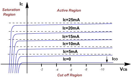
The collector current IC is completely determined by the input current IE and the VCB voltage. The relationship is given in fig. 2. It is a plot of IC versus VCB, with emitter current IE as parameter. The curves are known as the output or collector or static characteristics. The transistor consists of two diodes placed in series back to back (with two cathodes connected together). The complete characteristic can be divided in three regions.
Figure 7.2
(1). Active region:
In this region the collector diode is reverse biased and the emitter diode is forward biased. Consider first that the emitter current is zero. Then the collector current is small and equals the reverse saturation current ICO of the collector junction considered as a diode.
If the forward current IB is increased, then a fraction of IE ie. adcIE will reach the collector. In the active region, the collector current is essentially independent of collector voltage and depends only upon the emitter current. Because adc is, less than one but almost equal to unity, the magnitude of the collector current is slightly less that of emitter current. The collector current is almost constant and work as a current source.
The collector current slightly increases with voltage. This is due to early effect. At higher voltage collector gathers in a few more electrons. This reduces the base current. The difference is so small, that it is usually neglected. If the collector voltage is increased, then space charge width increases; this decreased the effective base width. Then there is less chance for recombination within the base region.
(2). Saturation region:
The region to the left of the ordinate VCB = 0, and above the IE = 0, characteristic in which both emitter and collector junction are forward biased, is called saturation region.
When collector diode is forward biased, there is large change in collector current with small changes in collector voltage. A forward bias means, that p is made positive with respect to n, there is a flow of holes from p to n. This changes the collector current direction. If diode is sufficiently forward biased the current changes rapidly. It does not depend upon emitter current.
(3). Cut off region:
The region below IE = 0 and to the right of VCB for which emitter and collector junctions are both reversed biased is referred to cutoff region. The characteristics IE = 0, is similar to other characteristics but not coincident with horizontal axis. The collector current is same as ICO. ICBO is frequently used for ICO. It means collector to base current with emitter open. This is also temperature dependent.