The ideal OPAMP :
An ideal OPAMP would exhibit the following electrical characteristic.
- Infinite voltage gain Ad
- Infinite input resistance Ri, so that almost any signal source can drive it and there is no loading of the input source.
- Zero output resistance RO, so that output can drive an infinite number of other devices.
- Zero output voltage when input voltage is zero.
- Infinite bandwidth so that any frequency signal from 0 to infinite Hz can be amplified without attenuation.
- Infinite common mode rejection ratio so that the output common mode noise voltage is zero.
- Infinite slew rate, so that output voltage changes occur simultaneously with input voltage changes.
There are practical OPAMPs that can be made to approximate some of these characters using a negative feedback arrangement.
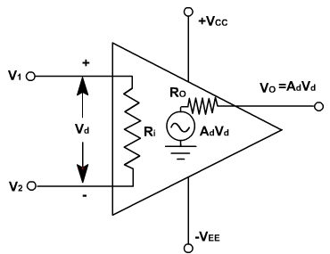
Equivalent Circuit of an OPAMP:
Fig. 5, shows an equivalent circuit of an OPAMP. v1 and v2are the two input voltage voltages. Ri is the input impedance of OPAMP. Ad Vd is an equivalent Thevenin voltage source and RO is the Thevenin equivalent impedance looking back into the terminal of an OPAMP.
Fig. 5
This equivalent circuit is useful in analyzing the basic operating principles of OPAMP and in observing the effects of standard feedback arrangements
vO = Ad (v1 v2) = Ad vd.
This equation indicates that the output voltage vO is directly proportional to the algebraic difference between the two input voltages. In other words the OPAMP amplifies the difference between the two input voltages. It does not amplify the input voltages themselves. The polarity of the output voltage depends on the polarity of the difference voltage vd.
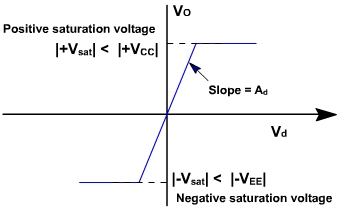
Ideal Voltage Transfer Curve:
The graphic representation of the output equation is shown in fig. 6 in which the output voltage vO is plotted against differential input voltage vd, keeping gain Ad constant.
Fig. 6
The output voltage cannot exceed the positive and negative saturation voltages. These saturation voltages are specified for given values of supply voltages. This means that the output voltage is directly proportional to the input difference voltage only until it reaches the saturation voltages and thereafter the output voltage remains constant.
Thus curve is called an ideal voltage transfer curve, ideal because output offset voltage is assumed to be zero. If the curve is drawn to scale, the curve would be almost vertical because of very large values of Ad.