Example 1 (Design)
Design an 11.3V regulated power supply shown in fig. 1 for a load current that varies between 400 mA and 500 mA. Assume an input of 120 V rms at 60 HZ into a 3:1 center - tapped transformer. Use a 12 V Zener with RZ = 2Ω. The transistor has VBE = 0.7 V and β = 100. Set C so Δvs= 30%.
Solution:
The design consists of choosing the values for Rsand for CF. First VS max is obtained multiplying the rms voltage by √2.
VS max = √2 x 120 = 170 V
The transformer output on either side of the center tap is one-sixth of the input, so VS maxis 28.3V.
Since Δvs= 30%,
Therefore, VS min= (0.7)(VS max) = 30%
Given that ILoad max = 500 mA
and ILoad min= 400 mA
VZ= 12 V
The maximum Zener current can be obtained from equation (E-3) derived in previous lecture,
Notice that the transistor keeps the value of IZ max quite small since β appears in the denominator.
The source resistance RS can be calculated from equation (E-1) of previous lecture,
Note that
The capacitor size is estimated from equation (E-5) of previous lecture:
Equation (E-7) can be used to evaluate the percent of regulation at the load.
Example 2:
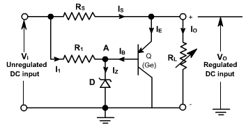
For the circuit of fig. 2, determine the following:
- Nominal output voltage
- Value of R1
- Load current range
- Maximum transistor power dissipation
- Value of RS and its power dissipation
The relevant information is as follows:
Vi = constant 8 V; D: 6.3 V, 200 mW; requires 5mA minimum current
Q: VEB= 0.2 V, hFE = 49, ICBO≈ 0
Fig. 2
Solution:
a. The nominal output voltage is the sum of the transistor's VEB and the Zener voltage:
V O = 0.2 + 6.3 = 6.5 V
b. R1 must supply 5mA to the Zener:
c. The maximum allowable Zener current is
P / V =0.2 / 6.3 = 31.8 mA
The load current range is the difference between minimum and maximum current through the shunt path provided by the transistor. At junction A, we can write
IB = IZ I1;
I1 is a constant 5 mA; thereforeIB =IZ I1 = (5 x 10⁻³ ) (5 x 10⁻³) = 0
IB =IZ I1 = (31.8 x 10⁻³) (5 x 10⁻³) = 26.8 mAThe transistor's emitter current is (hFE + 1) (IB). IB ranges from a minimum of around zero to a maximum of 26.8 mA; therefore the load current range is (hFE + 1) (26.8 x 10⁻³) = 1.34 A. The Zener alone could provide a maximum range of 26.8mA.
d. The maximum transistor power dissipation occurs when the current is maximum. Using IE ≈ IC, we have
PD = VO IZ = 6.5 (1.34) =8.7 W
e. RS must pass 1.34 A to supply current to the transistor and RL:
The power dissipated by RS is