Example-1:
- Consider the pulse generator shown in fig. 3. In the quiescent state (before a trigger pulse is applied), find V2, VO and V1.
- At t = 0, a narrow, positive triggering pulse v whose magnitude exceeds VR is applied. At t = 0+, find VO and V1.
- Verify that the pulse width T = RC ln (2 VO) / VR.
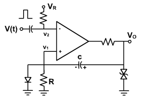
Fig. 3
Solution:
(a). Before a trigger pulse is applied, the circuit is in stable stage with the output at vO = +VO ( ≈ VZ + 0.7). The capacitor C is charged with the polarity shown in fig. 3.
Thus, v1 ≈ 0.7V
and v2 = -VR
(b). At t = 0, a narrow positive triggering pulse of higher magnitude is applied. The capacitor C voltage can not charge instantaneously. Therefore, v2 becomes positive and greater than v1 (≈ 0.7 V). The comparator output changes.
Thus, vO= - (VZ + 0.7V) = -VO
Since capacitor C voltage can not change instantaneously, therefore,
v1 = 2 VO
(c). The input trigger pulse is of very short duration therefore, after the short duration pulse the voltage v2 returns to (-VR). But the output remains VO because v1 is at 2VO.
The capacitor now starts charging exponentially with a time constant t = RC through R towards VO, because diode is reverse biased.
VC = (-VO VO) ( 1 e-t / RC ) - VO
The voltage at point v1 is, thus, given by
V1 = - VO vc
= - VO + 2 VO (1 e-t / RC ) - VO
= - 2 VO e-t / RC t / RC
When v1 voltage becomes more than VR, the comparator output switches back to +VO. Let at t = T, the voltage v1 becomes VR
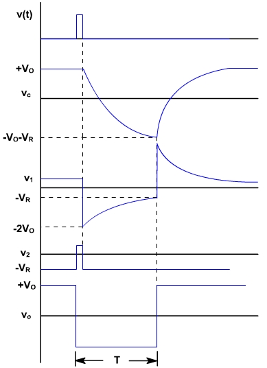
The capacitor now starts charging towards +VO through R until vc reaches +VO and v1 becomes 0.7 V. The waveforms at different points are shown in fig. 4.
Fig. 4