Triangular Wave Generator:
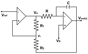
In the relaxation oscillator discussed in the previous lecture, capacitor voltage VC has a near triangular wave shape but the sides of the triangles are exponentials rather than straight line. To linear size the triangles, it is required that C be charged with a constant current rather that the exponential current through R. The improved circuit is shown in fig. 1.
Figure 21.1
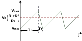
In this circuit an OPAMP integrator is used to supply a constant current to C so that the output is linear. Because of inversion through the integrator, this voltage is fedback to the non-inverting terminal of the comparator rather than to the inverting terminal. The inverter behaves as a non-inverting schmitt trigger. The voltage vR is used to shift the dc level of the triangular wave and voltage vs is used to change the slopes of the triangular wave form is shown in fig. 2.
Fig. 2
To find the maximum value of the triangular waveform assume that the square wave voltage vOis at its negative value = -Vsat. With a negative input, the output v (t) of the integrator is an increasing ramp. The voltage at the non-inverting comparator input v1 is given by
When v1 rises to VR, the comparator changes state from - Vsat to +Vsat and v(t) starts decreasing linearly similarly, when v1 falls below vR the comparator output changes from +vsat to -vsat. Hence the minimum value of triangular vmin occurs for v1 = vR. Hence the peak value Vmax of the triangular waveform occurs for v1 = VR.
Therefore,
The peak to peak swing is given by
The average output voltage is given by
.
If VR = 0, the waveform extends between -Vsat (R2 / R1 ) and +Vsat (R2 /R1).
The sweep times T1 and T2 for Vs = 0 can be calculated as follows:
The capacitor charging current is given by
where, vc = -vout is the capacitor voltage.
For vout = -Vsat,
. Therefore,
When the output voltage of first OPAMP is +Vsat, then, the voltage v1 is given by