Second Order Low-Pass Butterworth filter:
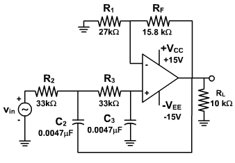
A stop-band response having a 40-dB/decade at the cut-off frequency is obtained with the second-order low-pass filter. A first order low-pass filter can be converted into a second-order low-pass filter by using an additional RC network as shown in fig. 1.
Fig. 1 Fig. 2 The gain of the second order filter is set by R1 and RF, while the high cut-ff frequency fH is determined by R2, C2, R3 and C3 as follows:
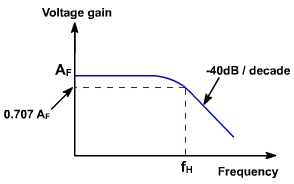
Furthermore, for a second-order low pass Butterworth response, the voltage gain magnitude is given by
where,
Except for having the different cut off frequency, the frequency response of the second order low pass filter is identical to that of the first order type as shown in fig. 2.
Filter Design:
The design steps of the second order filter are identical to those of the first order filter as given bellow:
.
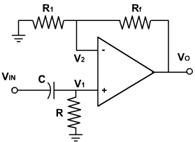
First Order High Pass Butterworth filter:
Fig. 3, shows the circuit of first order high pass filter.This is formed by interchanging R and C in low pass filter.
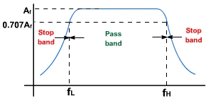
The lower cut off frequency is fL. This is the frequency at which the magnitude of the gain is 0.707 times its pass band value. All frequencies higher than fL are pass band frequencies with the highest frequency determined by the closed loop bandwidth of the OPAMP.
The magnitude of the gain of the filter is
Fig. 3
If the two filters (high and low) band pass are connected in series it becomes wide band filter whose gain frequency response is shown in fig. 4.
Fig. 4