First Order Low Pass Filter:
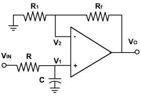
Fig. 2, shows a first order low pass Butter-worth filter that uses an RC network for filtering, opamp is used in non-inverting configuration, R1 and Rf decides the gain of the filter.
According to voltage divider rule, the voltage at the non-inverting terminal is:
Fig. 2
Thus the low pass filter has a nearly constant gain Af from 0 Hz to high cut off frequency fH. At fH the gain is 0.707 Af and after fH it decreases at a constant rate with an increases in frequency. fH is called cutoff frequency because the gain of filter at this frequency is reduced by 3dB from 0Hz.
Filter Design:
A low pass filter can be designed using the following steps:
- Choose a value of high cutoff frequency fH.
- Select a value of C less than or equal to 1 µF.
- Calculate the value of R using
.
- Finally, select values of R1 and RF to set the desired gain using
.
Example - 1
Design a low pass filter at a cutoff frequency of 1 kH z with a pass band gain of 2.
Solution:
Given fH = 1 kHz. Let C = 0.01 µF.
Therefore, R can be obtained as
A 20 kΩ potentiometer can be used to set the resistance R.
Since the pass band gain is 2, R1 and RF must be equal. Let R1 = R2 = 10 kΩ.