| |
| contd... |
| Region E: This region is defined by the input condition Vin >= VDD -Vtp, in which the pdevice
is cut off (Idsp =0), and the n-device is in the linear mode. Here, Vgsp= Vin - VDD
Which is more positive than Vtp. The output in this region is Vout=0 |
| From the transfer curve , it may be seen that the transition between the two states is very
step.This characteristic is very desirable because the noise immunity is maximized. |
| |
| 15.4 βn/βp ratio: |
| |
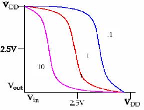 |
The gate-threshold voltage, Vinv, where Vin =Vout is dependent on βn/βp . Thus, for given process, if we want to change βn/βp we need to change the channel dimensions, i.e.,channel-length L and channel-width W. Therefore it can be seen that as the ratio βn/βp is decreased, the transition region shifts from left to right; however, the output voltage transition remains sharp. |
Figure 15.4: βn/βp graph |
|
| |
|
| |
| |
| |
| |
| |
| |
| |
| |
| |
| |
| |
| |
| |
| |
|