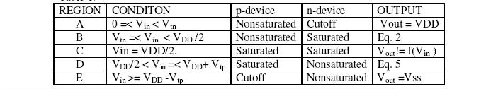
The operation of CMOS inverter can be divided into five regions .The behavior of n- and
p-devices in each of region may be found using
We will describe about each regions in details-
Region A : This region is defined by 0 =< Vin < Vtn in which the n-device is cut off (Idsn
=0), and the p-device is in the linear region. SinceIdsn = –IIdsp, the drain-to-source current
Idsp for the p-device is also zero. But for Vdsp = Vout– VDD, with Vdsp = 0, the output
voltage is Vout=VDD.
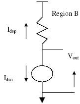
Region B : This region is characterized by Vtn =< Vin < VDD /2 in which the p-device is in its nonsaturated region (Vds != 0) while the n-device is in saturation. The equivalent circuit for the inverter in this region can be represented by a resistor for the p-transistor and a current source for the n-transistor as shown in fig. 6 . The saturation current Idsn for the n-device is obtained by setting Vgs = Vin . This results in
and Vtn =threshold voltage of n-device, µn=mobility of electrons
Wn = channel width of n-device &Ln = channel length of n-device
The current for the p-device can be obtained by noting that Vgs =( Vin – VDD ) and Vds = (Vout – VDD ). And therefore,
and Vtp =threshold voltage of n-device, µp=mobility of electrons, Wp = channel width of n-device & Lp = channel length of n-device. The output voltage Vout can be expressed as-
Fig 15.31: Equivalent circuit of MOSFET in region B