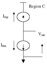
Region C: In this region both the n- and p-devices are in saturation. This is represented by
fig 7 which shows two current
sources in series The saturation currents for the two devices are given by
.
This yields,
By setting,
Which implies that region C exists only for one value of Vin. We have assumed that a MOS device in saturation behaves like an ideal current soured
with drain-to-source current being independent of Vds.In reality, as Vds increases, Ids also increases slightly; thus region C has a finite slope. The significant factor to be noted is
that in region C, we have two current sources in series, which is an “unstable” condition.
Fig 15.32: Equivalent circuit of MOSFET in region C
Thus a small input voltage as a large effect at the output. This makes the output transition very steep, which contrasts with the equivalent nMOS inverter characteritics. characteritics. The above
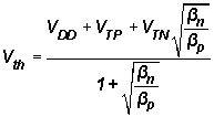
expression of Vth
is particularly useful since it provides the basis for defining the gate
threshold Vinv which corresponds to the state where Vout=Vin .This region also defines the
“gain” of the CMOS inverter when used as a small signal amplifier.
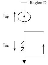
Region D: This region is described by VDD/2 <Vin =< VDD+ Vtp.The p-device is in saturation while the n-device is operation in its nonsaturated region. This condition is represented by the equivalent circuit shown in fig 15.33 .The two currents may be written as
with Idsn = -Idsp.
The output voltage becomes
Fig 15.33: Equivalent circuit of MOSFET in region D