Lecture 15 : Impedance Matching using Transmission Line
Single-Stub Matching Technique
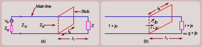
A stub is a short-circuited section of a transmission line connected in parallel to the main transmission line. A stub of appropriate length is placed at some distance from the load such that the impedance seen beyond the stub is equal to the characteristic impedance.
Suppose we have a load impedance connected to a transmission line with characteristic impedance (Figure a). The objective here is that no reflection should be seen by the generator. In other words, even if there are standing waves in the vicinity of the load , the standing waves must vanish beyond certain distance from the load.
Conceptually this can be achieved by adding a stub to the main line such that the reflected wave from the
short-circuit end of the stub and the reflected wave from the load on the main line completely cancel each other at
point B to give no net reflected wave beyond point B towards the generator.
We make use of Smith chart for this purpose
Since we have a parallel connection of transmission lines, it is more convenient to solve the problem
using admittances rather than impedances. To convert the impedance into admittance also we make use of the
Smith chart and avoid any analytical calculation.
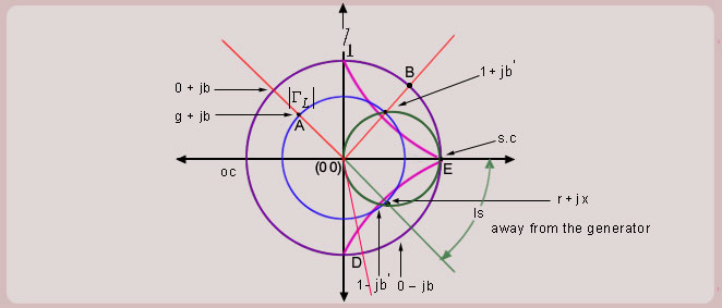
Now onwards treat the Smith chart as the admittance chart
Matching Procedure
First mark the load admittance on the admittance smith chart (A).
Plot the constant circle on the smith chart .Move on the constant
circle till you intersect the constant
circle this point of intersection corresponds to point
(B). The distance traversed on the constant circle is . This is the location of placing the stub on the transmission line from the load end .
Find constant suseptance
circle.
Find mirror image of the circle to get
circle.
Mark
on the outer most circle (D).
From (D) move circular clockwise upto s.c point (E) to get the stub length
.
Advantage
The single-stub matching technique is superior to the quarter wavelength transformer as it makes use of only one
type of transmission line for the main line as well as the stub. This technique also in principle is capable of
matching any complex load to the characteristic impedance/admittance. The single stub matching technique is
quite popular in matching fixed impedances at microwave frequencies.
Drawback
The single stub matching technique although has overcome the drawback of the quarter wavelength transformer technique, it still is not
suitable for matching variable impedances. A change in load impedance results in a change in the length as well as
the location of the stub. Even if changing length of a stub is a simpler task, changing the location of a stub may not
be easy in certain transmission line configurations. For example, if the transmission line is a co-axial cable,
the connection of a stub would need drilling of a hole in the outer conductor.