| |
Impedance Matching |
| |
|
|
Impedance matching is one of the important aspects of high frequency circuit analysis. To avoid reflections and for maximum power transfer the circuits have to be impedance matched. |
|
|
|
Transmission line sections can be used for the purpose of impedance matching. |
| |
|
|
There are various impedance matching techniques which are discussed in the following : |
| |
|
| |
Quarter Wavelength Transformer |
| |
|
|
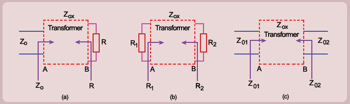
This technique is generally used for matching a resistive load to a transmission line (a), for matching two resistive loads(b),or for matching two transmission lines with unequal characteristic impedances (c) (see Figure). All cases are identical in principle as all require matching between two purely resistive impedances. |
| |
|
|
| |
|
|
Principle |
|
|
|
Introduce a section of a transmission line(called transformer) between two resistances to be matched, such that the transformed impedances perfectly match at either end of the transformer section. That is, in Figure (a) say, the impedance seen towards right at A should be  , and impedance seen towards left at B should be R. So when seen from transmission line side it appears to be terminated in , and impedance seen towards left at B should be R. So when seen from transmission line side it appears to be terminated in  , and when seen from load resistance side it appears to be connected to a conjugately matched load R. Similar is true for Figure (b,c). , and when seen from load resistance side it appears to be connected to a conjugately matched load R. Similar is true for Figure (b,c). |
|
|
|
For the transformer we have two parameters to control, characteristic impedance of the transformer section, and the length of the transformer section. |
| |
|
|
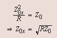
Let us assume that the characteristic impedance of the transformer section is  . For . For  length, the transformer inverts the normalized impedance. Therefore the impedance seen at A towards right in Figure (a) would be length, the transformer inverts the normalized impedance. Therefore the impedance seen at A towards right in Figure (a) would be |
|
|
For matching at A,  should be equal to should be equal to  , i.e. , i.e. |
| |
|
Conclusion |
 |
|
Two resistive impedances can be matched by a section of a transmission line which is quarter-wavelength long and has characteristic impedance equal to the geometric mean of the two resistances. |
|
|
The quarter wavelength transfer is commonly used at the junction of two transmission lines of unequal characteristic impedances. |
|
|
|
Drawback |
|
This technique needs special line of characteristics impedance  for every pair of resistances to be matched. for every pair of resistances to be matched. |
|